Sam's is your source for Hatteras and Cabo Yacht parts.

Enter a part description OR part number to search the Hatteras/Cabo parts catalog:

Email Sam's or call 1-800-678-9230 to order parts.

GM Windlass 32 v Up/Down wiring diagram

  • Thread starter Thread starter Aussie Mike
  • Start date Start date
  • Replies Replies 23
  • Views Views 3,554

Aussie Mike

Member
Joined
Mar 4, 2011
Messages
35
Status
  1. OWNER - I own a Hatteras Yacht
Hatteras Model
63' COCKPIT MY (1985 - 1987)
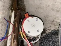
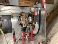
Can anyone point me in the right direction for a wiring diagram for 32v GM windlass with 2 solenoids.
Thanks in advance
 
Call Rick at GalleyMaid. He'll email it to you.
 
I just pulled one off my 46. It had a jumper from one post to another as mine only had a foot switch for up. But after looking at the diagrams it seems any will do up and down if wired so.
 
Don't have a diagram but its fairly simple. I had a foot switch go out and reversed two of the small solenoid wires so the "down" button became "up" until I could get home and get a new switch. I think mine has the diagram on the back of the electrical panel cover. Did you check there?
 
Are you having issues that require getting into this?
The kids at Galley Maid are great on the phones also.
 
It has a down button, but the book says to use the clutch and free fall the anchor down...... So when does one use the down button?
 
It has a down button, but the book says to use the clutch and free fall the anchor down...... So when does one use the down button?

The issue has been discussed many times. The GM doesn’t have a bearing to handle load on the way down so they recommend using free fall by releasing the clutch. With light load using power down is fine according to Rick at GM
 
It has a down button, but the book says to use the clutch and free fall the anchor down...... So when does one use the down button?
One of our customers had an issue with his GM. After a gear replacement and other repairs, he was reminded to lower by free falling lots more than power down.
Seems the gear back lash was not designed for pushing, just pulling. So, start if off the pulpit, then let loose slowly and set scope slowly were instructions.
These are still 50+ year old designs. Bless them for making a fine pulling winch, but read your manual, not for paying out.

There is a big and finely built wrench for slacking the clutch nut. I had to build the customer a new wrench.
These days, All is good.

Mind you, days in the rain, yes, drop that anchor electrically, that is why it is there. Very small reverse duty cycle.
 
I don't think you have to worry about powering down. Use it until you have an issue and then have it rebuilt. Most won't ever use it enough to ever have a problem. I had GM rebuild mine 17 years ago and I've been powering it down ever since. If it lasts 20 years before rebuild, I'll be happy. What else can you buy today that lasts that long?
 
Call Rick at GalleyMaid. He'll email it to you.


I emailed Rick at GM about 4 days ago and he has not replied.

Both up and down worked on mine until the solenoids burned out. I just wanted to make sure the marine electrician wired them correctly.
 
I don't think you have to worry about powering down. Use it until you have an issue and then have it rebuilt. Most won't ever use it enough to ever have a problem. I had GM rebuild mine 17 years ago and I've been powering it down ever since. If it lasts 20 years before rebuild, I'll be happy. What else can you buy today that lasts that long?
Their running out of some parts. I have sold back good parts after upgrades. They will soon have issues rebuilding older products.
This includes Ideal products also.
 
Thanks for the feed back. The clutch tool is in the deck box. I'll be using it.
 
What is this clutch tool you speak of?
 
I emailed Rick at GM about 4 days ago and he has not replied.

Both up and down worked on mine until the solenoids burned out. I just wanted to make sure the marine electrician wired them correctly.

I spoke with Rick about 3 weeks ago. We discussed rebuilding mine but turned out the rubber motor coupling washer just needed replacing from previous owner powering down. He told me then he was going on vacation in a week and couldn't get to rebuilding it before my trip. If he took 2 weeks off he probably wont be back until Monday.
 
I'm calling BS on this parts shortage. Those are easily machined parts that any machine shop can make. GM may not want to take time to make them, but anyone can do it.
 
I was hoping someone would have the diagram so I wouldn’t have to crawl in my anchor locker...

Here you go ...

Motor has four terminal numbered A1 A2 F1 F2. See position based on the thermal cut off (2 thin wires being at 12 O’clock) Negative from battery goes to F2. See motor picture below. Note that picture posted rotated 90 degrees...

Solenoids have 2 terminal at each end, one in the rear, one in the front. Positive cable from the battery and breaker is attached to the TOP REAR of both solenoids.

The BOTTOM REAR of both solenoids are connected together and go to F1 on the motor

Both forward terminal of the right most solenoid are connected together and go to A1 on the motor

Both forward terminal of the left solenoid are connected together and go to A2 on the motor

Note that in my relay box the linkage between solenoid terminals use a copper bat.

Switches wiring to follow
 

Attachments

  • 5E693D76-936D-4092-AE68-706926D4696F.webp
    5E693D76-936D-4092-AE68-706926D4696F.webp
    22.5 KB · Views: 36
  • BAEDEAE4-6FAE-410C-8049-D65B1A7397CA.webp
    BAEDEAE4-6FAE-410C-8049-D65B1A7397CA.webp
    21.2 KB · Views: 36
I would like to add some windlass controls on my lower helm. What’s involved with this?
 
Now for the control switches. At the top of each solenoid you have two smaller terminal. The terminals on the right side are both connected to the negative from the batteries

From the switches terminal of the breaker, power for the switches go to the therma Cut off switch on the motor and comes back to a terminal strip. From there power goes to switches, either foot switches on deck or a helm switch. Or ideally both. From the switches, power comes back to each solenoid left side small terminal

The part I don’t remember and can’t check without pulling out the solenoids is which way they are supposed to be facing :(
 
I would like to add some windlass controls on my lower helm. What’s involved with this?

Pretty easy. You need to send a triplex cable to the helm. One wire connected to the power feed. The other two from the switches are connected to the same terminals coming back from the foot switches
 

Forum statistics

Threads
38,152
Messages
448,690
Members
12,482
Latest member
UnaVida

Latest Posts

Trending content

Back
Top Bottom