Sam's is your source for Hatteras and Cabo Yacht parts.

Enter a part description OR part number to search the Hatteras/Cabo parts catalog:

Email Sam's or call 1-800-678-9230 to order parts.

Why It Takes Me Forever To Get Anything Done.

  • Thread starter Thread starter Avenger
  • Start date Start date
  • Replies Replies 53
  • Views Views 28,626
I meant it might make it to the NE rendevous, but if you want to see her before that and you're ever around Amityville let me know. I wouldn't make a seperate trip for it though. It's still very much a work in progress. SLOWWW progress. :rolleyes:

Got Ya

O.K just making sure your going to try to make it by boat this year ;)

Slowwww progress is better then No progressssss :)
 
Why I'm Not Going To The Airshow This Weekend.

Well, since everybody else seems to have cool boating projects going on I thought I'd resurrect this thread to prove that I still work on my own boat. I never seem to get to use it, but I do seem to work on it a lot.

I guess I probably should have looked into the injection pumps a long time ago. However I'm not really that excited to add more work to the to-do list, so I thought if they ain't broke.... Well, one of them broke. And like shoes you don't buy just one.

Since I have a connection at a fuel injection shop I had the opportunity to rebuild these myself, and in the rich tradition of yachtsmanbill I took pictures. So I thought I'd share something of the mysterious "dark art" of fuel injection with the HOF.

This wasn't the one that was acting up, but it managed to create its own set of problems. It was stuck in the engine and I kept breaking the puller bolts trying to separate it from the drive gear.
3208-01.webp

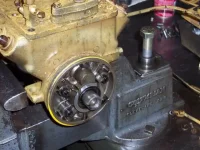
So here's "Trick of the trade" #1: The tapered drive is actually a sleeve that is pressed onto the camshaft and by threading a bolt into it you can force it off the pump. After that it popped right out of the gear. In this pic you can see the old sleeve with the forcing bolt still in it on the vise, and the splined end of the camshaft that it is pressed onto. Be careful not to strip the threads in the sleeve, but otherwise don't worry about damaging the sleeve, they're a one-shot deal and get replaced anyway.
3208-02.webp

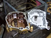
Once you get all of it apart you start cleaning. Governor housings before and after. All that varnish is mostly a product of sitting around. So who still thinks you don't need an additive with a cleaning agent?
3208-03.webp

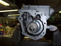
"While we're in there" we might as well do some updates. This pic shows the back flange of the camshaft and the thrust area in the pump housing where it rides.


jb5pwCu.jpg


Arrrghhh! 4 image limit. To be continued...…

***Site only allows 3 uploaded images vs 4 hosted. Working on a solution for that.***
 
Last edited:
Part Deux

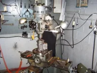
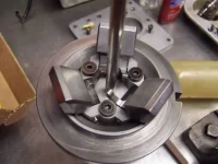
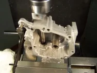
There's not a lot of end-loading on these but it's still steel against iron lubricated only by diesel fuel. CAT later added a bronze thrust washer to the design. So it's off to the Bridgeport to set up and machine a pocket in the housing to accept the washer. It sounds easy, but there's a lot of time and frustration in getting everything centered up and measured so the counterbore is the right depth and diameter.

3208-05.webp

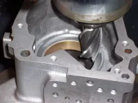
Run an end mill around it a few times:

3208-06.webp

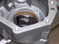
You also need to spot and pocket the housing for the bearing's anti-rotation tab:

3208-07.webp

Viola! In thrust we trust:

O5uzQEO.jpg


Stand by.....
 
Last edited:
Tres

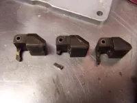
Now we've arrived at the original problem that got this whole mess started. The stbd engine had a wild barking surge at idle. It also had a tendency towards unlimited RPM at the top end. Of course it's my luck to have what may be the only broken governor weight in 3208 history but it does explain the symptoms:

3208-09.webp

The fix, three fresh shiny weights attached to the camshaft.

3208-10.webp

While we're fiddling with the governor and we have a Bridgeport available we're going to add two other updates. Boring the housing to accept a steel throttle shaft bushing on "the other end." The original design only had one on the lever end. Since these engines aren't in a truck where the driver is sawing it up and down constantly to change gears it's not much of an issue, but hey.. "While you're in there."

3208-11.webp

There's also a minor mod to install a pressurizing valve in the housing that we'll see later. So now we've got all the pieces cleaned and ready to assemble:

CkxCdZg.jpg


Stay tuned.....
 
Last edited:
Part IV

The camshaft goes in, then the gear pump goes together on the front of that. Once that's in the new drive sleeve is installed and the lifters get installed in their bores.

3208-13.webp

On the back end the governor springs and levers go in place and get linked to the fuel control racks:

3208-14.webp

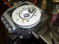
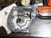
Here's the governor cover, now with two throttle shaft bushings and throttle shaft installed. Toward the upper right you can see the little brass pressurizing valve. It's in a passage that leads to the suction side of the gear pump. I think CAT was concerned that if the fuel system became restricted the pump would suck air through the throttle shaft seal so they put in what is basically an anti-siphon valve.

3208-15.webp

Now comes the heartbreakingly tedious process of setting the levers that control the pumps for each individual cylinder. The racks get locked in position and a gauge is installed in each bore.

Then the lever is positioned and clamped onto the rack. CAT wants each one set within +/- .01mm as shown on the indicator. Each graduation on the indicator is .002mm which is equal to about .00078 inches. I, being insane, want them all at zero since the more balanced the delivery between cylinders the smoother the engine will run. Call it "Blueprinting" an injection pump.

Did I mention that the readings change when you torque the levers? They do, but not all the same amount. Not only is each lever different, there's no guarantee that any one will change by the same amount each time. After 16 of these one usually wants to start drinking heavily.

WVjjn1W.jpg


We pause briefly for station identification.....
 
Last edited:
What Are We Up To? Part 5

It gets easier from here. After the levers are set the individual pumps are installed and now we set the full load stop. This is the collective maximum rack = maximum fuel delivery setting which determines engine power output. CAT has an interesting system that uses a rack dimension (which is how most manufacturers write their spec) but CAT uses electrical contact to determine when that dimension is achieved. The spec for these pumps is 4.35mm at contact.

Yes, I set it EXACTLY to 4.35mm. At least we're not splitting it into ten thousandths this time. Keep that little electrical contact in mind, it's going to come up in "trick of the trade" #2.


3208-17.webp


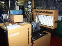
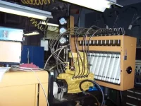
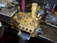
Now it's time for the test bench to see how well we did. If the settings were all done correctly the fuel deliveries should all be correct and there should be only one adjustment to be made on the stand. It's probably not obvious here, but the fuel deliveries were all very even. Here's a picture of one pump on the test bench and just for Ss & Gs I threw in a pic of big cousin CAT 3412 on the same bench.


3208-18.webp


3208-20.webp

More to come....
 
Last edited:
If you're still awake... Part 6: The Final Chapter

So the only adjustment that needs to be set on the test bench is the maximum RPM or high idle. BTW this is not true of most injection pumps. Other pumps are calibrated almost entirely on the test bench. The high idle needs to be set on the bench because it is a dynamic balance point between spring force vs centrifugal force from the governor weights.

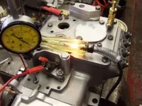
Remember that little electrical contact? "Trick of the trade" #2 is that most mechanical CAT governors have an electrical terminal to check that continuity. When weight force overcomes spring force the governor starts to pull the fuel back to limit the engine's RPM. When that happens the continuity of the full load stop breaks and your test light goes out. So for guys diagnosing power problems you can use that test light to see if the governor is in full load or not.

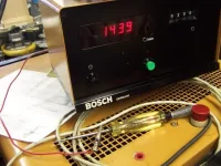
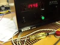
In this case we're using it to see what RPM the governor starts to break away or in CAT terms "Stabilization RPM". The spec calls for it at about 2880 engine RPM. Since the pump turns at 1/2 engine speed we're looking for contact to end just above 1440 RPM.

So, 1439 RPM, power is still on:

3208-21.webp

When RPM goes higher, the governor starts to pull back, away from the full load contact:

3208-22.webp

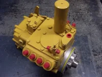
That's what that's about. Pull 'em off the bench, wash 'em and paint 'em and we should have two purrrrfectly matched CATs purring away under the salon floor. And hopefully two injection pumps that I'll never have to fark with again.

3208-23.webp

I hope you've enjoyed the chance to see something we don't usually get to see. Of course, I haven't finished installing them yet so instead of doing the Airshow it looks like I'll be working on the boat. :rolleyes:
 
Last edited:
had one rebuilt for a customer a few months back and it was full of varnish and 4 of the 8 passages blocked. The shop here that did it did a great job too and suggested ATF to clean the sludge in the fuel system.
 
Scrod - you should open up a shop and do this kind of thing for a living! Thanks for sharing, I know I was curious as to what happens when I sent my fuel injection pump out for repair over winter.
 
had one rebuilt for a customer a few months back and it was full of varnish and 4 of the 8 passages blocked. The shop here that did it did a great job too and suggested ATF to clean the sludge in the fuel system.
My preference is Stanadyne Performance Formula, especially for the cetane boost. We didn't run much of it through these pumps so I can't say one way or t'other if it would have cleaned them up. You're looking at almost thirty years worth of goo. That's not going away in a couple of tankfuls.

ATF.... Well, it's supposed to have lots of detergents in it, so it could work. At worst it's like chicken soup. It can't hurt.
 
Yes, you ARE nuts but it's a great kind of nuts. Nice shop, by the way. How much does the Bridgeport mill weigh, I'm curious.
 
Thank you, I think. :)

IIRC the manual says it's 2000 lbs. Being on my second one (had one, found another one that although older was near perfect so I sold the 1st one) and having moved them around a few times I'd say the manual is pretty accurate.
 
Simply Awesome Scrod! good job!
 

Forum statistics

Threads
38,154
Messages
448,708
Members
12,482
Latest member
UnaVida

Latest Posts

Trending content

Back
Top Bottom