Nick in Manitou
Active member
- Joined
- Jan 15, 2019
- Messages
- 140
- Status
- OWNER - I own a Hatteras Yacht
- Hatteras Model
- 53' EXTENDED DECKHOUSE (1983 - 1988)
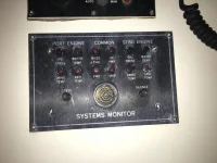
I finally pursued the Systems Monitor - INOP situation on our boat. It turns out that these things don't work if you remove the fuse...
I installed the fuse and at first nothing happened - which I thought was a good thing. Then, after a few minutes, sitting with a cocktail in my hand, the system started sort of cackling. It became more frequent as we sat there and occasionally we could see the Bilge Level light flicker. I went into the starboard engine room and lifted the float and the system responded appropriately with a light and the alert horn.
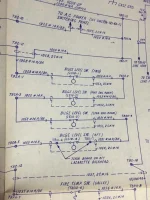
I checked the drawings that I received with the boat and "32 V. D.C. Ship's Batteries, Elementary Diagram" (CN-101-ED) (Sheet 2 of 2) refers me to CN-107-ED for the "Systems Monitor 12 Point Elementary Diagram". I have attached a photo of the Bilge Level Switches area on that drawing and have a question...
It has been about 47 years since I worked with electrical schematics and I want to be sure that I am correct in thinking that the drawing shows that the circuit is normally closed and would alarm if the circuit was open. Is that what is shown on the drawing?
If there is a bad connection somewhere between the float switches and the systems monitor, or a defective float switch, or a problem in the systems monitor box itself, these could all be causes for the intermittent alarm...is that the case?
Anyone had a similar experience with this portion of the system and have any suggestions? I have read here on the forum that there is a fellow that works on these, but before I send it off to someone else, I figured that I should check for the simple stuff first.
Thanks!
Nick
I installed the fuse and at first nothing happened - which I thought was a good thing. Then, after a few minutes, sitting with a cocktail in my hand, the system started sort of cackling. It became more frequent as we sat there and occasionally we could see the Bilge Level light flicker. I went into the starboard engine room and lifted the float and the system responded appropriately with a light and the alert horn.
I checked the drawings that I received with the boat and "32 V. D.C. Ship's Batteries, Elementary Diagram" (CN-101-ED) (Sheet 2 of 2) refers me to CN-107-ED for the "Systems Monitor 12 Point Elementary Diagram". I have attached a photo of the Bilge Level Switches area on that drawing and have a question...
It has been about 47 years since I worked with electrical schematics and I want to be sure that I am correct in thinking that the drawing shows that the circuit is normally closed and would alarm if the circuit was open. Is that what is shown on the drawing?
If there is a bad connection somewhere between the float switches and the systems monitor, or a defective float switch, or a problem in the systems monitor box itself, these could all be causes for the intermittent alarm...is that the case?
Anyone had a similar experience with this portion of the system and have any suggestions? I have read here on the forum that there is a fellow that works on these, but before I send it off to someone else, I figured that I should check for the simple stuff first.
Thanks!
Nick