Sam's is your source for Hatteras and Cabo Yacht parts.

Enter a part description OR part number to search the Hatteras/Cabo parts catalog:

Email Sam's or call 1-800-678-9230 to order parts.

starting problem on gasser

  • Thread starter Thread starter UNIQUE_NAME
  • Start date Start date
  • Replies Replies 85
  • Views Views 17,845
mike:
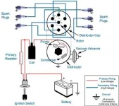
the good stb eng shows 6v ign on, didn't check while cranking. port eng shows 0v unless i physically ground the coil negative, then it shows 6v.
when i first hooked up the timing lite to the problematic port engine coil wire and cranked, the lite was sporadic at best. since moving the coil wires around there is NO spark from the coil. i have tried 2 new coils and swapped the ballast resister with the stb engine, all with the same results.

according to my schematics. 1 negative coil feed comes from inside the dist, which it does. the other goes to a ground bus. if i run a jumper wire from the coil negative to ground i get the 6v across the coil with ign on. when i found this is thought i had it solved, but still no spark when i crank. rather vexxing...

one other thing, on the good stb engine the dist housing has a braided wire screwed to the side. this braid is about 18" long and mechanically grounded to the block. the coil negative wires are run thru the middle of the braid for about 1', exit and go to the coil. the problematic port engine has the same setup except the braid is not grounded other than laying on the block.
any ideas on the purpose?

sorry for the long winded response, but i know someone has had whatever this problem is before and sooner or later something i say will ring a bell.
thanks for the patience.

jim
 
From your description it does sound like there is no ground on the primary side of the ignition.

Inside the distributer, on the advance plate - where the points or pickup coil is mounted, there is frequently (depending on dist design) a braided ground wire that attaches the plate to the distributer case. Make sure it is properly attached. The EXTERNAL braided wire that is laying on the block (it should be bolted) ensures that the dist case is grounded. If it isn't grounded (to the block), it won't trigger the coil because, as you noted, there is no ground. Distributers don't always have this braided ground, assuming that there will be proper electrical connection from the physical attachment of the dist to the eng. This is a reasonable assumption when the parts (block/dist) are new but is problematic as the parts age and corrosion/varnish/whatever intrude on the base of the dist (often aluminum). The ground strap is a better way!

NOTE that depending on the design of the electronic module replacement, the pickup coil may or may NOT ground to the advance plate. Some do, some don't. If it doesn't, then grounding the distributer separately isn't necessary. I realize there are a lot of "depending"s here but there are various designs for these things.

Look at the internals in the working distributer and see if the non-working ones are the same. But as noted, it could be the module or the pickup coil itself.

I know it can be frustrating dealing with ignition electrical issues. As you noted, often the problem is staring you in the face! I have a lot of gas engine experience but couldn't begin to count the number of times I got it wrong initially or looked at something difficult when the answer was actually easy and obvious! It's USUALLY easy though not always obvious, especially if your mind is already aimed in another direction due to description, advice, etc, But - the number of times an engine problem turns out to be some serious mechanical issue is extremely low.


Good Luck!!!
 
there is no ground strap inside the dist but i will connect the outside braid to ground anyway.
i never really understood the mechanics of how he coil fired, it just did or it didn't. but think i'm starting to understand.
the coil fires BECAUSE of the making/breaking of the circuit NOT because there is power to it, kind of like a wire sparks when first connected. the points/module close completing the circuit causing the coil to spark. so in theory i should be able to take a stand alone coil, apply power to the + side of the coil and quickly connect/disconnect a ground wire and produce a spark from the coil. is that about right?

something else mentioned about the resister being out of the circuit during cranking. shouldn't that mean there should be a wire from the momentary push button to the coil + to bypass the resister and supply 12v during cranking? the "ign" wire should be connected to the resister which would supply about 6v during running then? i have 3 wires (dist feed and 2 others) feeding the resister.

thanks

jim
 
Jim,

Right! The coil fires when the connection is broken from the points/pickup coil. It then recharges when the connection is made. Obviously, this happens REALLY fast! :)

Yes, there will be a circuit that, when the start switch is engaged, bypasses the resistor. How this is wired will, again, depend on the specific setup. There is usually an ign 1 and 1gn 2 terminal that perform the function you describe - when the start button is depressed, full battery power is supplied to the coil. The three wires at the resistor are usually:

One from the resistor to the coil;
Another one to the SAME terminal on the resistor as the one to the coil - this is from the starter circuit and provides full battery voltage (bypasses the resistor) WHEN THE STARTER IS ENGAGED.. The third wire, which is on the other end of the resistor, is from the alternator/batt and provides the normal voltage to operate the ignition AFTER it is started. Since it travels through the resistor, it reduces the voltage on the other end and, subsequently, to the coil.
 
Can you take some pics or at least tell what kind of electronic igition system is installed?

The system is really quite simple and thus the problem can't be too complicated.

Like Mike said, you just need +6 or 12 volt to positive side of the coil and the "switch" in the distributor switches the negative side to ground (thus collapsing the field in the coil and thru induction making a nice high voltage...think of it as making fake AC current).

The "switch" in the distributor has to be grounded (already said) and depending on the system, sometimes you can put a test light or use a multimeter to see if the neg side of the coil is actually closing to ground during crank (not really possible on newer modules because many do multiple sparks).

I know on merccruiser junk you can diagnose whether it is the coil, module, or sensor ("switch") by disconnecting the switching wire and striking it to ground while holding the high tension coil wire near ground. If it sparks, then u got bad sensor. If it doesn't, move on to next step and check module etc. It's almost always the sensor.
 
mike:
i have 3 wires connected to one side of the resister, the other side has 1 wire that goes to coil +. nothing else is on coil +. of the 3, one is the dist
wire, one shows 12v with ign on and the other is probably the starting ciruit. (i was alone again so i couldn't test for power and crank) the good stb engine is wired the same. i traced the mystery wire and it goes down were the starter solenoid is and winds back up on a + bus bar. i expected it to be wired to the solenoid switch. if the mystery wire does in fact turn out to be the starting circuit, i will change the configuration to what you described.

krush:
it's a pertronix, 2 wires out of the sensor and pickup that is mounted under the rotor. i've swapped out everything except the sensor with no change in results. tonight, when i hooked the timing light to the coil/dist wire while cranking. it only showed a couple of sporadic flashes and then stopped. the good stb motor shows a consistent flash. it seems process of elimination leaves the sensor.

oh, and i tried the stand alone coil theory i described earlier and it did produce a spark.

am i missing anything else?

thanks,

jim
 
I agree, it sounds like the pickup module in the distributer...

If both engines are wired the same way, don't change any wiring on the "bad" engine since the other is doing fine. I would bolt down that braided ground though. As I said, there are a variety of configurations depending on the engine/ignition unit. My description was of a fairly common method used on (originally) non electronic domestic engines but they are NOT all the same. For several years Mopar used a ballast resistor with 4 individual terminals and associated differences in the circuitry.
 
so it seems my coil would never get 12v with the current wiring. wouldn't that hinder the coil from making a better spark during starting?

jim
 
I also have pertronix, never her of one going bad but if you have the old model, Pertronix I then if you left the key on for more than 15seconds without motor running then you may have burned it out.

We purchased Pertronix coil, low resistance so we bypassed the resistor. get full voltage to coil.

I think that the pertronixII is a better unit. if you forget to turn off the key then it will shut down and not get damaged.
 
As described, it does sound like the coil would never get the full 12V for starting but that really seems unlikely unless someone modified the wiring.

The wire bypassing the resistor may not be attached to the resistor but may go directly to the coil from the start circuit.

Coils that don't use an external ballast resistor actually just have an internal resistor that serves exactly the same purpose. I don't know of any coils that actually use the full voltage of the car's system through the coil for normal running of the car - just starting. If the coil was wound to accept full voltage all the time, they would provide sufficient spark for running but NOT for starting.
 
thanks for the advise, i was wondering what the difference was between the I and II's

jim
 
As described, it does sound like the coil would never get the full 12V for starting but that really seems unlikely unless someone modified the wiring.

THAT could never have happened


The wire bypassing the resistor may not be attached to the resistor but may go directly to the coil from the start circuit.
only 3 wires on the coil, resister wire on + and 2 on the ground.
also nothing attached to resister wire on resister.
 
There should be a switched hot on the + side of the coil that is momentary with the starter. The ground side usually has only 1 wire.
 
i believe the momentary switched is one of the 3 attaced to the resister. nothing but the resister wire on the coil. the 2 wires to the coil - are, 1 the dist module negative, and 2 coil ground.

jim
 
That sounds right - the 2nd wire on the neg is probably the Tach.

The one wire on the + indicates that the circuit from the starter switch has one wire that goes to the resistor, then to the coil +. Then there is another wire from the starter switch which is connected to the wire from the resistor to the coil at some point in the harness.

A pic would be helpful - my attempt at explaining is starting to confuse myself! I'll see if I can find a generic diagram on the web...

Here's one - shows points but that doesn't matter...
 

Attachments

  • IgnitionDiagram.webp
    IgnitionDiagram.webp
    15.5 KB · Views: 44
Last edited:
on my setup, i believe that red middle wire coming out of the switch connnects to the same place on the resister the left red wire connects to.

jim
 
Does the resistor have two terminals or 3? You may have already said but I don't recall.

I can't see how it can work properly if it only has two terminals - one in/one out - and BOTH wires from the start switch go the resistor's "in" terminal AND there is only one wire coming from the resistor to the coil.

But as we have all noted, I may be missing something obvious here.

In any case, IF the other engine is wired exactly the same way and works fine, who are we to argue with success? Disconnect the wires on the pickup coils in both distributers and do a OHM check on each. Off hand I'd think the reading should be around .04 to .08 ohms but I can't say for sure. But if they are noticeably different - especially if the bad one has no reading - it would indicate the pickup coil has gone south!
 
2 terminals on the resister. yes it works, but it might also explain why it is
harder to start in the colder weather.

jim
 
Put the momentary switched wire on the output of the resistor.
 
"Put the momentary switched wire on the output of the resistor"

Good idea - but if it works, it would indicate that someone changed the wiring at some point. I've seen dumb PO stuff but I can't figure out why anyone would change the wiring to that configuration if it wasn't oem. What the heck would be the point?

It would be good to have a Crusader engine wiring diagram - I used to but gave all the service manuals away when I sold my previous boat.
 

Forum statistics

Threads
38,156
Messages
448,748
Members
12,482
Latest member
UnaVida

Latest Posts

Trending content

Back
Top Bottom