I still plan on letting you all know the results of the inspection by a qualified technician, but I am still waiting for the technician to find time to come out to check the boat.
The response from the company which installed the generator intrigues me, and I would appreciate your comments:
"this unit was hooked up like the previous unit had been installed.
We did not alter the wiring on the boat or
generator but followed the hookup according to the previous generator.
Based on the picture attached the unit was hooked up to produce 120 volts as the previous unit was. We can tell it was 120 volt based on the wiring to the breaker."
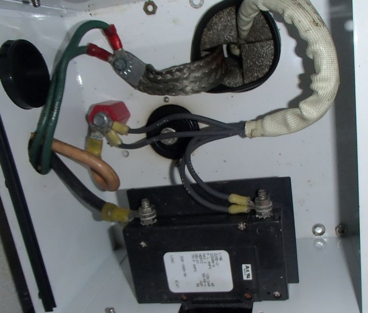
I understand that the generator is wired to the boat as 120v. I thought a generator set up at the factory as 120/240 had to be modified with jumpers or otherwise, within the generator before it could be wired to the boat as 120 in the manner shown in the photos. As I read the Onan diagram, I thought the four output wires for the generator should be connected as shown in the diagram with wires T-1 and T-4 connected to separate poles of the double pole breaker on the generator, rather than two wires ( T-1 and T-3) connected together to one breaker pole. I understand that with 120/240 the Hot/Load output wires would need to be kept separate, one to each of the two 30 amp panels.

Is there a difference between how the generator is set up for output ( 120 vs 120/240) or is it simply a matter of how the generator is wired to the boat wiring?
The seller/installer advised the following regarding the neutral / ground connection:
"The generator is grounded at the braided strap coming out of the unit and is attached to the green wires that lead to a ground on the boat. The neutral wire (yellowish/white wire) is hooked up to an isolator (red post). The boat must have been setup to have an isolated neutral."
I have checked the connections with my multimeter and confirmed that there is no continuity between the neutral buss and the grounding buss with the shore power rotary switch turned to "generator" (with shorepower and inverter disconnected and the generator turned off)
As best I can understand, the ABYC requires a neutral / grounding connection at the generator. Did Hatteras set up their generators with an isolated neutral? ( The boat does not have an isolation transformer.)
Thanks


