Sam's is your source for Hatteras and Cabo Yacht parts.

Enter a part description OR part number to search the Hatteras/Cabo parts catalog:

Email Sam's or call 1-800-678-9230 to order parts.

Inverter wiring to breaker panel

  • Thread starter Thread starter scottwvyc
  • Start date Start date
  • Replies Replies 11
  • Views Views 9,716

scottwvyc

Active member
Joined
May 15, 2005
Messages
98
Hatteras Model
37' CONVERTIBLE (1977 - 1982)
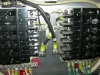
I would like to install my Heart Freedon 20 charger/inverter (2000w). I think I have most of it figured out with the exception of wiring the panel. My panel, as you can see in the picture below, is split into two sides. I only want inverter power going to boat's recepticles to run the tv, microwave, and coffee maker, ect. The top breakers on each side are the breakers for the recepticles and are ground fault protected, the other breakers are ganged together and power the water heater, stove, and AC side of the fridge ect. My question is, how do I "split the panel" to power those top two breakers and not the rest, yet still power the recepticle breakers when I am hooked to shore power or running the generator?
Thank-you
Scott
 

Attachments

  • breaker panel.webp
    breaker panel.webp
    61.5 KB · Views: 138
As I think about this more I may be able to answer my own question.If I isolate those top two breakers and supply them with power from the inverter/charger only, when I am on shore power or running the generator, does 110v pass through the inverter/charger to power those loads? Or would they then become inverter only loads?
 
Unless your inverter has a built in relay, You will have inverter power only on those circuits. You could add a relay or a switch and drop out the inverter whenever there is a shore or generator power president.


BILL
 
What you are describing is essentially the way my (Outback) inverter is connected to the panel - wired to several specific breakers. But unless the inverter has a "pass thru" circuit, you will only have power to the specific breakers when the inverter is actually on and battery power is being supplied to it. Obviously, the power available will depend on the pass thru - the Outback is 30A at 120vac.

Before I installed the Outback, I had the original inverter which was installed by the dealer when the boat was new in 1980. They also installed a separate relay to manually select either the inverter or shore/genny power for the selected circuits. I removed all that extra wiring and the external relay when I installed the OB. The original inverter would drain the batt bank in around 6 hours just at idle, with no loads! Two years ago, on the exact same batteries, the Outback ran for 36 hours powering the fridge with the boat our of the water and was still going when I put the boat back in the water and connected shore power.
 
do you have the maniual for the inverter? it's really all explained in there, if you dont' have it you can download it from the Xantrex website.

I have a freedom 30, which is basically the same as yours...

what you do is isolate the breakers that power the items you want inverter powered from teh rest of the breakers. To do that, you either group them together and then isolate the feed bar which links the breakers or you disconnect them and use jumpers around the other ones

Next step is to add a 30amp breaker to the original group. From that breaker you go to the INPUT 1 on the inverter, then connect OUTPUT 1 to the breakers you isolated for you inverter power items

Since the freedoms have 2 inputs, you can significantly increase charge time by connecting the second input to a second 30amp breaker. This gives you a full 30 amp dedicated to charging, instead of sharing the 30amp with your inverter powered loads.

Finally, connect the neutrals and ground.

About Neutral, i did split the neutral on my boat so that the inverter power circuits neutral were separated from the other ones. This is how the diagram shows it, although some believe it's not necessary since the inverter bonds ground and neutral anyway, so it's all connected.

but again, the Freedom manual is clear and shows you different wiring options.
 
All the above is good advice...Pascal posted: "..you can significantly increase charge time.."
but I think he meant "reduce charge time" or "increase charge power" ....
the relay function you need, the "pass thru" of shore power to inverter powered loads is referred to as "transfer" function in the Xantrex manual...USE THE MANUAL, it's excellent and unless you are a wiring design expert will give you some ideas you likely had not thought about. As Pascal noted, Note that you assign a number of circuit breakers.... for transfer, load and charge functions...more than you might think.....and note the dc fuse and lead length requirements...

A weakness in all inverters is that if the inverter fails, you likely lose inverter and shore power transfer function....so what you connect to the inverter matters in concept. Similar to you, I powered only several (galley) accessories and an extra receptacle which I installed. I figured if the inverter failed, I could just plug in my microwave and coffee maker to a separate receptacle powered directly from the genny...

I chose to run my TV from a separate stand alone 400 watt inverter because it was inexpensive and I could turn it on only when viewing TV...Running a small TV from a big inverter is often inefficient but may not matter depending on how you boat is used...genny running in particular and frequency of load use....and the idle standby current drawe of your inverter....just 1.5 idle current standby 24 hours daily makes a noticeable difference....36 amp hours!! Freedoms are not the most efficient standby power consumers!!!
 
Last edited:
I just finished AC wiring side of Xantrex Prosine 2000w inverter last weekend. My panel is slightly different than yours, but I found it easeist to rearrange the breakers so that one side is fed only by Inverter (lights, outlets, and fridge for me) and other side (oven, water heater, battery charger) only by shore side or generator. I am going to make new labels for breakers with P-touch label maker at work for front side of panel. For the same reason everyone else is mentioning, you don’t want to put too much load thru bypass relay on inverter. There was a previous post in past thread where someone found the bypass relay actually welded shut because too much load passed thru when on shore power.

Rob, think worth mentioning that at least for the Xantrex, it actually operates more efficiently at lighter loads then at full loads. I have seen previous post saying you didn’t want to oversize your inverter because of belief that it operated more efficiently as it reach it max rated output. Not the case for Xantrex Prosine series according to the efficiency curve given in manual (maybe square wave inverters operate more efficiently at max output?).
 
You don't have seperate breakers for all the items you want to run. So your probably going to want to put the recpticles and lights breakers on the inverter circuit. To do this or to isolate any breaker you choose you simply cut that leg off the common bar. That will disconect that breaker from the common feed and you can then wire it to inverter output.

Brian
 
" Not the case for Xantrex Prosine series according to the efficiency curve given in manual (maybe square wave inverters operate more efficiently at max output?)..."

Not so...better look at that efficienc y curve again: http://www.xantrex.com/web/id/241/docserve.aspx page 83.....but it's less variation than I might have thought....not really significant in the scheme of power planning....only about 5% off max....ALL INVERTERS OPERATE AT MAXIMUM ACTIVE EFFICIENCY IN THE MID RANGE OF THWEIR POWER RATING

but IDLE POWER for the Prosine is 60 WATTS....I take that to be at 12 volts, or 5 amps...quite high!!!!! UGH!!!!! anmd not reflected in the above "efficiency" figure.

And beware:

Usually, inverters have poor ACTUAL efficiency at low loads compared to rated loads....despite manufacturer claims....say you are running a 250 watt TV: then a quarter or so of your "load" is the "idle current" and in addition there is likely the usual 15% or so losses when the inverter is operating...so you are losing 35% or 40% of your battery power to "losses" !!!.....

It's also important to have an idea how efficiency is determined by the manufacturer (I do not know, but I bet they don't count idle time and idle current): for example if your leave a Prosine idle all day that's 5 amps times 24 hours or 120 amp hours load....that by itself is about 3/4 of my actual daily load...

Last time I checked, a while ago, their TRACE line had the lowest idle current (power) draw...
 
Last edited:
Great point made about idle power consumed. Probably worth a phone call to vendor (Xantrex) in this example to see if they include that in the efficiency curve. The curve is a little better for the Prosine 2.0 at low load (chart below from page A-5 of users manual). They list the no load power input power on this model as 25W which is certainly better than 60W. Sorry scottwvyc, didn't mean to go off on tangent - hopefully get some more input on your question.
 

Attachments

  • Inverter.webp
    Inverter.webp
    8.7 KB · Views: 98
Thanks everyone for the helpful advice. I have one more question, the manual instuctions say I should ground the chassis of the inverter to an AC ground on the boat. What would be an acceptable AC ground in or around the engine room?
 
It's best to run the ground to the common ac ground in the panel. Ron
 

Forum statistics

Threads
38,156
Messages
448,748
Members
12,482
Latest member
UnaVida

Latest Posts

Trending content

Back
Top Bottom