Sam's is your source for Hatteras and Cabo Yacht parts.

Enter a part description OR part number to search the Hatteras/Cabo parts catalog:

Email Sam's or call 1-800-678-9230 to order parts.

Inverter Installation Question

  • Thread starter Thread starter Vincentc
  • Start date Start date
  • Replies Replies 23
  • Views Views 8,799

Vincentc

Legendary Member
Joined
Jun 3, 2008
Messages
1,514
Status
  1. OWNER - I own a Hatteras Yacht
Hatteras Model
43' DOUBLE CABIN (1970 - 1984)
I am trying to complete the installation of a Magnum 2812 inverter this morning. As I was tightening the connections to the 12v breaker between the battery bank and the inverter, the wrench made contact with both poles to the breaker. Even though they are both positive there was an arc when the wrench made the connection. The cable is connected to the inverter and the breaker is off.


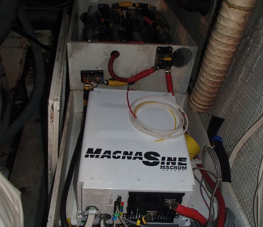
The inverter is close to the exhaust leak and there is still soot to be cleaned.

I checked things with a volt meter and it registered 11 volts when connected to the the battery side of the (positive) breaker and the positive post on the inverter. I have doubled checked the inverter post and it is connected to the positive post.

The manual states " a brief spark or arc may occur when connecting the battery cables to the inveter DC terminals; this is normal due to the inverter's internal capacitors being charged."

Therefore is seems OK, however, the fact that the voltmeter repeatedly reads 11 volts between two positive poles worries me. Magnum customer service is closed until Monday, and I would like to finish the installation today, but I do not want to destroy the inverter or worse.

Can anyone advise whether or not I should go ahead and turn on the breaker?
 
If you connected one probe of the meter to the battery side of the breaker and one probe to the positive post of the inverter, the 11 volts you are measuring is the difference in voltage between those two points.

If you arced across the terminals when attaching the cables - breaker was off, I assume - you put a partial charge into the inverter capacitors because you essentially turned it on for a split second, probably not long enough to fully charge the caps. The 11 volts is the difference between the battery voltage and whatever is present in the inverter circuit (capacitors) at the moment.

Since all you did by arcing across the inverter was to turn it "on" for an instant, there is no way you could have caused any damage ASSUMING it all happened as you describe.

Check the wiring again to be sure it is all correct in accordance with the inverter wiring instructions and turn on the breaker!
 
One of your test leads should go a power source(+) and one to ground, in order to get a voltage reading. Therefore I don't understand why you are getting a voltage reading between the posts of the circuit breaker unless one is inadvertently grounded. If you want to check the function of the breaker, then check the resistance between to posts. It should read 1 when open and 0 or close to that when closed.
As far as checking voltage is concerned, start at the battery and then check each post from the battery to the inverter. The voltages should be the same. If not, there is some resistance somewhere in that line (unlikely).
As far as shorting across the breaker, I doubt that any damage was done, so I think that you are just not using your meter correctly.
 
One question I have is what is the breaker you have in there? The 2812 specs a 400 amp time delay "T" fuse in your application.
 
"Therefore I don't understand why you are getting a voltage reading between the posts of the circuit breaker unless one is inadvertently grounded"

Basically, it's a voltage drop reading. With the breaker open, and the probes touching as he described, the voltage reading is the difference between battery voltage and the voltage in the inverter. If the breaker is turned on, there would (should) be no voltage reading between those two posts unless there is a wiring connection problem or high resistance in a cable. Neither is likely in a new installation.

I should have added that as Greg pointed out, the voltage check as described doesn't really do anything helpful unless you truly are attempting to perform a voltage drop test.
 
Last edited:
One question I have is what is the breaker you have in there? The 2812 specs a 400 amp time delay "T" fuse in your application.

I wanted a switch as well as a fuse, and in order to avoid two sets of connections chose a circuit breaker. The largest circuit breaker I found was a Blue Sea 200 amp. Since my largest expected intermittent load is about 1200 amps ( coffee maker or microwave), I assume 200 amps DC with additional intermittent capacity should take care of that. I used 2/0 cable between the batteries and the inverter since they were so close, but am going to change that to 4/0 per advice from Magnum.

If the 200 amp breaker causes problems, I will change it. I see the 200 amp creating convenience, but not safety issues.

I have not put power to the inverter. I used the multi meter to see there might be some short between the positive and negative terminals, and the ohm meter appeared to indicate some resistance, I believe it read .4 or so. I moved on to completing the wiring for the AC sub panel and intend to recheck for a short today. It is raining and no chance for using the boat.

Thanks for the input


breakers have a line side and load side which is like polarity. A charger / inverter should not have a breaker. The 2
00 is large enough but you need a 400 amp breaker and a switch to handle at least that on a constant basis.
 
"there might be some short between the positive and negative terminals, and the ohm meter appeared to indicate some resistance, I believe it read .4 or so."

What resistance range are you on? If it's an auto-ranging meter it will adjust itself to whatever range needed to come up with a reading. Depending on the internal circuitry of the device in question, there will frequently be resistance between hot and ground. Devices with transformers, for example, typically do that. Remember that autoranging meters are "trying" to find something - ANYTHING to display. It can be confusing if you don't notice what range the meter has shifted to. There is a huge difference between .4 Ohms and .4 milOhms (.0004 ohm)

If you are concerned that you have made some error in installation then it would be best to consult someone locally who is knowledgeable who can come aboard and check it out. The problem with troubleshooting via internet is the possibility for misunderstanding by the various parties involved. IOW, maybe I misunderstand what you are saying or you may have forgotten to mention some related part of the problem. If you are uncomfortable at all with the work you did and don't feel any of the suggestions received here are helpful or that they could be wrong, call someone in who is knowledgeable to check it out.

Good Luck!
 
It is an auto ranging meter.
I rechecked the terminals and the meter consistently gave the same reading as it did when the probes were touching nothing. I also turned it to "beep" when the probes touched each other, and not a sound when I touched the probes to the positive and negative posts on the inverter.

I went ahead and turned the breaker on and nothing bad happened, except nothing happened. The batteries have been sitting up a while and perhaps the voltage (12.15 v) was too low. I will charge the batteries and try later.

I have a fuse and a switch and will probably switch out the breaker.

Thanks
 
As you explain the problem it does not sound like any damage should have occurred. When checking on a system like you are installing, using the voltage setting on the meter, it is best to put the negative probe on the source negative, like the wire going directly to the battery negative terminal. Using this method, with the breaker off check the voltage on the wire coming from the battery, if should be battery voltage, now turn on the breaker, and measure the voltage on the other connection on the breaker, it should read the same on both terminals. If you think there is sufficient charge on the capacitors to give you a reading, you can either turn the breaker off and recheck the voltage at than point, or disconnect the wire on the load side of the breaker, and recheck.

I would be hesitant to just put in a fuse and switch, the breaker is a safety device to protect the equipment, a fuse my not blow as fast a the breaker can open, this could compromise the protection needed for the equipment.


No a breaker is not the recommended safety for a charger / inverter. First of all the fuse size should be 400 amps. Second a breaker is calibrated for only one direction. You will electrons flowing both ways.
 
No a breaker is not the recommended safety for a charger / inverter. First of all the fuse size should be 400 amps. Second a breaker is calibrated for only one direction. You will electrons flowing both ways.

I had to go back and recheck the picture, I was thinking the breaker was included in the inverter. Why a fuse would be recommended, I don't understand, but a fuse where the breaker is located will certainly work OK.

As for your second comment about a breaker being calibrated one way, is a theory that is way beyond my understanding, never heard it, and don't get it. Do you have a reference that explains it.
 
I had a breaker reversed on an inspected vessel and was told to reverse it. I contacted the manufacturer's engineering department and they explained the trip apparatus was designed for a single direction on dc breakers and that it would probably trip in the other direction at about the same amperage but would not be within the design tolerances of the breaker. May take more or less in the other direction .
 
Thanks Scott, that's a new one on me. It kind of makes sense though for a dc breaker. I don't know why anyone would reverse line and load anyway, if they do they have no business working on it in the first place.
 
some breakers are mirror images of others and can be mixed up pretty easily if your eyes are not great in the dark
 
Trying to help people on this forum has gotten ridiculous, it seems someone always knows more than the next guy, if they don't, you get some off the wall smart a$$ remark, or some kind of theory that is not pertinent to the problem. I can not say I have ever seen a quality circuit breaker that is not clearly marked line and load, and if is not marked clearly don't buy it, it is junk. It doesn't seem like a wise idea to work on electrical equipment in poor or insufficient light.

To get back to the subject at hand, Vincent how are you making out with the inverter? If I can be of help PM me, and it can probably be easily solved with a phone call. If you decide to go with fuses, check with the manufacturer to clarify what type of fuse to use. They probably specify what type in the manual. It can make a difference.
 
Thanks,
Job work has been interfering with boat work . The battery bank had sat up and gone down. Once I get it charged I will see if everything works. Magnum seems insistent that I use 400 amp protection, either fuse or breaker. For now, I intend on checking the breaker flow and see if it all works.

Regards
 
Trying to help people on this forum has gotten ridiculous, it seems someone always knows more than the next guy, if they don't, you get some off the wall smart a$$ remark, or some kind of theory that is not pertinent to the problem. I can not say I have ever seen a quality circuit breaker that is not clearly marked line and load, and if is not marked clearly don't buy it, it is junk. It doesn't seem like a wise idea to work on electrical equipment in poor or insufficient light.

To get back to the subject at hand, Vincent how are you making out with the inverter? If I can be of help PM me, and it can probably be easily solved with a phone call. If you decide to go with fuses, check with the manufacturer to clarify what type of fuse to use. They probably specify what type in the manual. It can make a difference.

Craig the older airpax uses the dame form factor as a carling but the poles are reversed. Also the marks are sometimes molded on the black plastic and almost impossible to read in less than bright perfect light.

Fuses do not care about polarity. There is not a trip mechanism. They also do not reset so spares are a must..
 
Thanks,
Job work has been interfering with boat work . The battery bank had sat up and gone down. Once I get it charged I will see if everything works. Magnum seems insistent that I use 400 amp protection, either fuse or breaker. For now, I intend on checking the breaker flow and see if it all works.

Regards

A 400 amp breaker costs as much as the whole system. Get the T fuse and block Magnum specifies, they sell one but others do too. Just do a search on 400 amp T fuse.
 
A 400 amp breaker costs as much as the whole system. Get the T fuse and block Magnum specifies, they sell one but others do too. Just do a search on 400 amp T fuse.

That explains why I didn't find a 400 amp breaker. Magnum appears to sell a mounting panel which includes a breaker, but I have not seen it for sale. I have a the fuse assy and switch but thought a 200 amp breaker would serve. Not a big deal to change. Practice makes it easier if not perfect.

Regards
 

Forum statistics

Threads
38,156
Messages
448,741
Members
12,482
Latest member
UnaVida

Latest Posts

Trending content

Back
Top Bottom