Sam's is your source for Hatteras and Cabo Yacht parts.

Enter a part description OR part number to search the Hatteras/Cabo parts catalog:

Email Sam's or call 1-800-678-9230 to order parts.

Boat AC ground wire not connected??

  • Thread starter Thread starter brico
  • Start date Start date
  • Replies Replies 32
  • Views Views 5,584
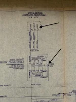
Tim, where is the transformer wired in at? Before the power panel or after? I would expect before and as close to the shore hookup as possible. Are the two hookups (port and starboard) just both wired directly to the transformer (with fuses of course)?
 
I hope this does not deviate too much from the questions in the original post.
I too hate it when someone high-jacks the thread.

On my boat, 1979 53' MY.
  • I have two sets of two 220-240 volt, 50 amp shore power connections.
  • One set of the two shore power plugs on the port side and one set of two on the starboard side.
  • On both sides there are 4 shot gun style fuse holders (two for each 50 amp input).
  • The 50 amp plugs feed each pair of shot gun fuses first.
  • Then the output of each shot gun fuse pair goes to the ship's power selector panel by the helm to feed the various sector switches.
  • From the selector switches the lines go to each of the two transformer inputs. Mine are located in the generator room below the galley, just in front of the engine room bulk head.
  • The output wire from the transformers come back up to the ship's power selector panel to supply the main breakers
  • From the output of the breakers at ship's power selector panel it feeds the various 120/240 breaker panels on the boat.
  • The transformers input is 220-240 VAC and outputs two 120 VAC (two legs with common neutral) and a single 220-240 VAC for the high voltage equipment
My boat also has the ability to accept a single 120 VAC 50 AMP shore power input (one on each side of the boat) that also feeds the ship's power selector panel and then to the transformers.
This allows me to connect to an old school 120 VAC power pedestal and make my own 120/240 VAC power but a very reduced load capability. This is really great when on the hard or at an older marina were only a 30 amp shore power is available.
This a different story.

My electrical system is all factory original and not modified.
 
I would highly recommend contacting Hatteras to find out about your particular boat. On my 1979 53 MY, my electrician almost crapped himself when he found this exact situation. After contacting Hatteras directly they confirmed that when my boat was made this was the correct wiring. The on board transformers took care of the ground. I don't pretend to understand it but after doing some extensive research with ABYC my electrician agreed that at the time is was up to the standard and we decided that after 40+ years of functioning properly we'd leave it as it was designed. YMMV

Not sure if you are saying that you also have the ground Green wire not connected at the back of the shore line plug leading onto the transformer (which is what I've found on my boat) and that Hatteras said it was OK. Here are some photos to make it clearer.
First Photo shows the Hatteras blueprint showing the path and connections for the shore line plug and lead to the Transformer.
Second one shows what I've found at the back of the shore line plug Green line not connected.
Third one shoving other end of that green line connected at the Transformer casing bolt as per drawing.
So, having it disconnected at the back of the shore line plug is against the original blueprint drawing schematic.
 

Attachments

  • IMG_2643 5.webp
    IMG_2643 5.webp
    93.8 KB · Views: 43
  • IMG_2652.webp
    IMG_2652.webp
    90.2 KB · Views: 43
  • IMG_2655.webp
    IMG_2655.webp
    94 KB · Views: 46
The pedestal wiring should never be altered. The wiring for no transformer, polarized transformer, or isolation transformer should always be done at the transformer. Imagine if the next person plugs into that pedestal thinking it is grounded?
 
Your diagram shows the transformer wired in polarization mode. Having the ground wire not connected is isolation mode. There are advantages and disadvantages to both.

In isolation mode, your boat is isolated from the dock and other boats which avoids the effect of galvanic corrosion. However, if your transformer should develop a short to the case, then someone swimming near your boat could possibly be electrocuted.

In polarization mode, as in your diagram, the ground wire is connected and now you lose the isolation that prevents galvanic corrosion, but you avoid the possibility of electrocuting a swimmer.

Regardless of which method you choose, you wouldn't disconnect the ground at the pedestal. You would disconnect it at the transformer.
 
The pedestal wiring should never be altered. The wiring for no transformer, polarized transformer, or isolation transformer should always be done at the transformer. Imagine if the next person plugs into that pedestal thinking it is grounded?

By pedestal wiring I assume you are thinking of the pedestal on the dock where shore power cord is connected. In my case that was not altered. The first photo is the back of the box / shore plug on the boat where I connect the shore power line, and that is where Green wire was not connected.
 
By pedestal wiring I assume you are thinking of the pedestal on the dock where shore power cord is connected. In my case that was not altered. The first photo is the back of the box / shore plug on the boat where I connect the shore power line, and that is where Green wire was not connected.

Oh, ok.
 
Not to shore ground.

Yes, all of the transformer cases are connected to shore ground, both polarization and isolation. Just look at your Hatteras schematics.
 
If you look at Tim's diagram, the shore side ground goes to a shield and the chassis to the boat side ground, and the two are not connected. That is the advantage of using an isolation transformer in a boat, you are entirely isolated electrically from the other boats. If you connected the shore ground and the boat ground to the chassis, then you have defeated that purpose.

https://www.passagemaker.com/technical/the-ins-and-outs-of-shorepower-transformers

This next link describes the differences between polarization and isolation transformers. The key difference is how the shore ground is connected. The first schematic is identical to the OP's schematic, while the second is identical to Tim's.

https://www.deimarine.com/media/wys...ation_vs_Isolation_Exchange_Article_10-20.pdf

It seems that the OP is using a regular transformer as an isolation transformer by not connecting the ground. However, a true (marine) isolation transformer has a shield, separate from the chassis that is connected to the shore ground.

Are these standards newer than the boats we are talking about? It seems isolating the ground to avoid galvanic corrosion is a pretty old concept.
 
I think those look right and like Hatteras did it originally. I think the shield is grounded in case of a short in the transformer.
 
Last edited:
Not sure if you are saying that you also have the ground Green wire not connected at the back of the shore line plug leading onto the transformer (which is what I've found on my boat) and that Hatteras said it was OK. Here are some photos to make it clearer.
First Photo shows the Hatteras blueprint showing the path and connections for the shore line plug and lead to the Transformer.
Second one shows what I've found at the back of the shore line plug Green line not connected.
Third one shoving other end of that green line connected at the Transformer casing bolt as per drawing.
So, having it disconnected at the back of the shore line plug is against the original blueprint drawing schematic.

Yes, that is what I'm saying. We found the exact same thing you did at the back of the shore line plug. Call Hatteras and give them your hull ID and discuss it with them.
 
The pedestal needs a ground in case something shorts out inside the pedestal. The onboard transformer needs a ground in case something shorts inside the transformer. The two grounds ie the one in the shore power pedestal and the one in the onboard transformer are not connected, they are "isolated" from each other. This is how Hatteras wired the boats that I have owned. A good way to think about the shore power ground is that it is a "common ground" shared by all the other grounds connected to that ground bus, that is all the other boats connected to it also, the only thing my boats have been connected to were the two hots (blk/red) to make 240VAC...............Pat
 

Forum statistics

Threads
38,156
Messages
448,757
Members
12,482
Latest member
UnaVida

Latest Posts

Trending content

Back
Top Bottom