I should of mentioned also, self exciting alternators like these don't like battery (Diode) isolators and further need a manual sense connected to them.
12, 24, 32 as our boat, I wire all the same.
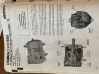
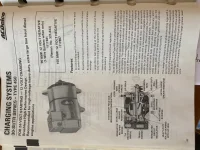
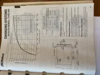
Please give the day to find or create a picture/diagram/schematic to display here.
I found (from the web and mfg notes) a way to help an alternator start charging when it is installed with Diode Battery isolators.
No feedback and the alternator does not enable well and may over charge.
Then I found (from the web and mfg notes), remotely enabled alternators from an ignition switch or run switch over charged its batteries because the voltage drop from the battery, to the helm switch then back to the alternator had a voltage drop and the regulator works extra hard to overcome this voltage drop, despite the battery was rite there, because of this long wire voltage drop, the alternator was trying to get that value up,,, and the battery was getting to much charge.
To manually enable a SI alternator and to keep from overcharging batteries, I install a fused feedback lead from the battery, thru a relay, to the battery sense lean on the SI alternator. It was a HOF member that turned me to the original 32V delco charging relay part number. Hope I can find that number part number again.
I have installed these lil kits on our 32V boat and many other 12, 24 & 32 boats thru the years.
I realized this evening in trying to offer a schematic, there is not a catch all answer to all SI or Leece-Neville (Prestolite) installations.
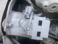
If after these comments you need more help, please send me directly your engine model and a picture of the back of the alternator. Please include the top connects of the voltage regulator IF any wires are attached.
If you can see it, those two flat pins may be connected by a similar molded jumper. Please state if you can see or ohm this out. My plan calls for this jumper to be cut
if not already.