Sam's is your source for Hatteras and Cabo Yacht parts.

Enter a part description OR part number to search the Hatteras/Cabo parts catalog:

Email Sam's or call 1-800-678-9230 to order parts.

1976 Hatteras 58 LRC Stabilizer System Install

  • Thread starter Thread starter JD5652
  • Start date Start date
  • Replies Replies 85
  • Views Views 9,865
As a side note... removal and reinstallation of the DC breakers is quite tricky. The outer mounting screw is difficult to get to and must be fully removed from the panel before you can remove the breaker. The inner mounting screw does NOT have to removed entirely, it can be loosened about 50% and the breaker will slide out. Be sure to de-energize the entire panel since you have to touch the live bus with the screwdriver in order to get to the mounting screws. Also, a "holding screwdriver" makes this job much easier.
 
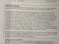
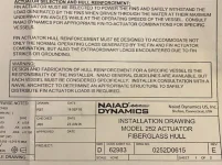
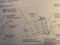
There was some discussion on the wood block mounting in previous posts. As discussed, there seems to be different methods for supporting the actuator/fin assembly.

As I was reviewing the NIAID manual last night, ran across a drawing that provides some insight as to the different support methods. See below for some excerpts from the drawing.

Niaid Support Mounting 02.webpNiaid Support Mounting 03.webpNiaid Support Mounting 01.webp
 
As noted, it is up to the installing shop to determine the best installation.
They seem to have done this before with happy customers.

However, that is the first time I have ever observed an internal block not glassed in.

A few other first (for me) on this install but again, they have done it before many times and Naiad authorized.
 
Last edited:
As noted, it is up to the installing shop to determine the best installation.
They seem to have done this before with happy customers.

However, that is the first time I have ever observed an internal block not glassed in.

A few other first (for me) on this install but again, they have done it before many times and Naiad authorized.

The glass is there I think..... with "Ample radius"..... Left margin, 3/4 down. That whole S-line just inside the circle is not the path to an item, it is the outline of the glass.
 
The glass is there I think..... with "Ample radius"..... Left margin, 3/4 down. That whole S-line just inside the circle is not the path to an item, it is the outline of the glass.

Oscar-

You are correct in that the block is glassed up each side and onto the inside of the hull.... it's just not glassed over the top of the wood block...
 
System commissioning was today. Ran into a couple problems, one a system configuration issue and one a little more complex.

For the complex one.. it was originally planned to take cooling water directly off the heat exchanger using one of the zinc locations. During system checkout, it was observed that we had no cooling water discharge overboard. We moved the pickup location to a spot immediately downstream of the raw water pump. This was still not sufficient "pressure" to push the water through the oil reservoir cooling coil. The oil reservoir/cooler is mounted about 4 feet above the cooling water pickup location. At this point it appears a passive method of scavenging cooling water from an existing location may not be feasible.

The next possibility is installing a dedicated cooling water pump for the stabilizer oil reservoir/cooler.

For those with stabilizer systems, was wondering how your oil cooling water systems are set up?.... a dedicated pump ... or scavenging off another system?

Thanks in advance!
 
As noted in previous post, had a minor configuration problem that turned out to be an ambiguous wiring drawing issue.

System has passed the operational portion of the check out. The decision has been made to install a dedicated electrical raw water cooling pump for the oil cooler.

Almost there!.....

Controller Pilot House Operational 01.webpController Pilot House Operational 02.webpController Pilot House Operational 03.webp
 
Interesting. Usually the zinc hole is used on the raw pump discharge.
However, later Hatts used a separate DCv or hydraulic driven water pump.
 
Sounds like airlock. It will probably work fine if you fill the lines and NAIAD heat exchanger thing with water.
 
I had cooling issues with the stabs when I bought my boat. It also has the HE tank mounted up high. I ended up pulling the raw water elbow right after the pump and brazing in a fitting to pull water from there. That was sufficient.

With my new engines, I'm going with a dedicated 12v bait well pump that Naiad uses for that purpose. It will be switched on with that engine. The key is to have the high temp alarm on the stabs just in case you ever lose water flow with that setup so you know to shut it down before you toast the oil.
 
Sounds like airlock. It will probably work fine if you fill the lines and NAIAD heat exchanger thing with water.

Thanks... we purged and primed the lines... still no love...
 
Interesting. Usually the zinc hole is used on the raw pump discharge.
However, later Hatts used a separate DCv or hydraulic driven water pump.

I had cooling issues with the stabs when I bought my boat. It also has the HE tank mounted up high. I ended up pulling the raw water elbow right after the pump and brazing in a fitting to pull water from there. That was sufficient.

With my new engines, I'm going with a dedicated 12v bait well pump that Naiad uses for that purpose. It will be switched on with that engine. The key is to have the high temp alarm on the stabs just in case you ever lose water flow with that setup so you know to shut it down before you toast the oil.

We tried the fitting immediately after the raw water pump as pictured below.... still no love... going with the dedicated 12V pump that will be wired with an oil pressure sensor on the engine. When the engine starts... the pump will start...

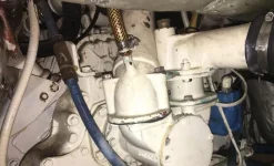
Zinc Raw Water Pump Intake.webp
 
On our recent install we did use a dedicated Oberdorfer pump plumed to an old unused thru hull, works great, plenty of water flow. John
 
I have a fitting welded to the raw water pump pipe just before the water enters the inter coolers . Works fine and good flow . There is a Naiad hydraulic powered pump for sale in E-Bay .
 
My NIAD stabs draw water from just before the heat exchanger utilizing the Zink hole, this is on DD 671ti. I have a good flow out the thru hull. Also after following this thread I now know that my stabilizers'/installed are worth about twice what we paid for the boat ..lol.. they surely do make the boat a pleasuer to run.
 
My NIAD stabs draw water from just before the heat exchanger utilizing the Zink hole, this is on DD 671ti. I have a good flow out the thru hull. Also after following this thread I now know that my stabilizers'/installed are worth about twice what we paid for the boat ..lol.. they surely do make the boat a pleasuer to run.

Interesting as that was the very first spot we tried to pull water from. My 671's are naturals and "may" not have the high flow water pump that TI's normally have. The ABT Yard Manager did say that they have used that spot successfully on DD 671's in the past.

I'm also pretty sure that the inlet location of the cooling water into the oil reservoir in also a factor. It's about 4-5 feet above the location of where we were trying to scavenge the water from. That's a pretty decent head to overcome where you're drawing from basically an open system that has little pressure to begin with. I'm not sure how many passes the heat exchanger is ... it appears to be a simple tube & shell design.

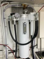
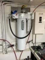
Oil Reservoir Mounted Piped and Plumbed.webpOil Reservoir Mounted 01.webp
 
I'm also pretty sure that the inlet location of the cooling water into the oil reservoir in also a factor. It's about 4-5 feet above the location of where we were trying to scavenge the water from. That's a pretty decent head to overcome where you're drawing from basically an open system that has little pressure to begin with.

That 4 or 5 foot of head ( 2 psi to overcome) sure may be the issue. Ours is about a foot or two below the tapped source and the exit out the thru hole is about three feet below.
 
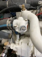
Here is a photo of the original water offtake on the starboard engine for the old Naiad 252 system that was originally installed in our 1984 boat.

The copper pipe goes about 1" into the cap fitting. It supplied the raw water just fine for the old Naiad and still does for the replacement Vetus system. Note, everything was level and there was minimal head. The hose travelled over the engine and along the wall at the same height to the Naiad 252 heat exchanger inlet.

If you do this, then you may not need the dedicated pump.

There is more at this link....

https://www.samsmarine.com/forums/s...Thickness-amp-New-Stabilisers-1984-61MY/page3

Congratulations on your new stabiliser system. It will make a huge difference.

vetus.webp
 
Last edited:
I do not like the idea of a brush/DCv motor trying to run near continuous duty pump vs lowering the head a bit to insure water flow when the engine (hydraulic pump) in in operation. IMO, not a real reliable set up with a brush motor.
If you have TA engines, it may be tight for another PTO point, TIs still have some options for another direct or belt drive pump.
Other options include the hydraulic pressure driving an other impeller pump as on some later Hatts.
 

Forum statistics

Threads
38,155
Messages
448,720
Members
12,482
Latest member
UnaVida

Latest Posts

Trending content

Back
Top Bottom