Sam's is your source for Hatteras and Cabo Yacht parts.

Enter a part description OR part number to search the Hatteras/Cabo parts catalog:

Email Sam's or call 1-800-678-9230 to order parts.

120v 50a

  • Thread starter Thread starter oscarvan
  • Start date Start date
  • Replies Replies 37
  • Views Views 7,290
We have a 1977, 58' yachtfish with same electrical panels a you posted. The 220v feed from port or starboard receptacles will feed through switch S5 both 110v legs and the 220v loads ( stove & washer/dryer). Looking at the electrical diagram,each 110v receptaclecan feed only 110v loads. One receptacle feeds one leg, the other would feed the other leg. Each leg is selected through S1or S2. But i cannot see that those two legs could be combined to create 220v.

That's what I was thinking.
 
Not sure if you'll be able to read this. I'm not 100% sure as the 5 position switches are quite intricate in pictorial format.... But I think it shows there is no pathway.
 

Attachments

  • IMG_9817.webp
    IMG_9817.webp
    79.9 KB · Views: 85
Not sure if you'll be able to read this. I'm not 100% sure as the 5 position switches are quite intricate in pictorial format.... But I think it shows there is no pathway.

You don't clearly see how S1 and S2 feeds S5 which then feeds the bus in that diagram?
 
You don't clearly see how S1 and S2 feeds S5 which then feeds the bus in that diagram?

Not really. The X-s indicate which connections are made with the switch in the various positions and then the lines on the left indicate which connection connects to which, and there are quite a few permutations.

I see the pathway from S5, with P or SB 220V, to S1 S2 and with those selected in 220V on to the 110 distribution panel. But I don't see the pathway to the 220V breakers from 110V selected on S1 to S5 and then on to the 220V breakers.
 
Last edited:
My schematic is on the boat, but there was enough of yours to figure out what is connected when.

S5 drives S1/S2, not the other way around.


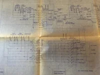
The AC breaker panel at the bottom has three inputs. L1, L2 and N. The 110v breakers on the left side are connected to L1 and N (giving 110v). The 110v breakers on the right side are connected to L2 and N (giving 110v). The 220v breakers at the bottom are connected to L1 and L2 (giving 220v). The 110v breakers and 220v breakers are all part of the same bus, they are not separate.

The distribution switches S1, S2 and S5 determine how L1 and L2 are powered. N is connected throughout the boat.

S1 determines if L1 is coming from the 220v source (S5), the port side 110v cord or the stbd side 110v cord.

S2 determines if L2 is coming from the 220v source (S5), the port side 110v cord or the stbd side 110v cord.

IF you are using a 220v source, then S5 determines if that source is the generator, the port side 220v cord or the stbd side 220v cord.

If you are using a 220v source, the flow is S5 to S1/S2 to AC breakers.

If you are using a 110v source, the flow is S1/S2 to AC breakers. (S5 doesn't matter).

The neutrals from all of these sources are tied together after the switches. On a boat, the ground is also connected to neutral.

Thus, you can have the following configurations.

1. The generator.
2. A 220v cord on either the port or stbd side (but not both).
3. Two 110v cords on either the port or stbd side.
4. One 110v cord on the port side and one 110v cord on the stbd side (different socket).

Obviously, options (1) & (2) will give you both 110v and 220v service. Options (3) & (4) will give you 220v service if the two 110v cords are out of phase.

If the two 110v cords are in phase, then you will not get 220v, however, the lines are still hot (meaning you can still get shocked), thus, I would flip the 220v breaker to off at the center bottom in that scenario. That way none of the 220v outlets in the boat will be hot, even though non functional.

One of the main design criteria of S1, S2 and S5, is that no source can (accidentally) be connected to another source, which would cause a major short. I would never have both 220v and 110v cords connected at the same time, but if you did, there is no switch combination (S1,S2 and S5) that would short them together. They could have done all of this distribution with no switches at all and just tied the L1, L2 and N directly to the plugs, and that would work as long as you only used the right combination of plugs at one time. Use the wrong combination, and poof. The only caveat to that is that you would NEVER want the generator connected with any shore power. So that would definitely require a transfer switch.

Also, while the whole boat shares a common neutral, that neutral is only connected to the appropriate source according to S1, S2 and S5. In other words, the sources are entirely isolated when not selected.
 
Last edited:
I think we are narrowing it down.

If you are using a 220v source, the flow is S5 to S1/S2 to AC breakers......The 110v breakers and 220v breakers are all part of the same bus, they are not separate.

Out of the bottom of S5 is a direct path to the "220V Distribution Panel and Bus" Out of S1 and S2 is a path to the L and R "Distribution Panel and Bus" (kinda missing on the schematic you can just see the top left corner of the left side coming down from S1)

This to me indicates that the 220V bus and the 110 buses are not connected.

So I believe that if there is 220V available S5 sends two phases to the 220V bus, and a single phase each up to S1 and S2 which in the 220V position send it to the respective 110V buses.

If there is (only) two times 110V available S1 and S2 are positioned accordingly, and there is no path back down to S5 and thus no path to the 220V distribution panel and bus.

I'll be on the boat this week to replace a battery bank and the mighty multi meter will tell. Since I don't have 120V/50A available I'll unplug the whole thing and use the continuity beeper.

On edit: Just received a blueprint of the AC distribution. It clearly shows the L1, L2 and 220V breakers/buses being separate, and states the feed for the 220V breakers is "from S5" If you pm me an email address I'll send it to you.
 
Last edited:
The mighty multi meter has spoken.

The S1 and S2 distribution buses are NOT connected to the 220V bus in any way except when The S1 and S2 Selectors are in the 220/110 position.

So when there's 240V available you select it on S5 which feeds the 220V bus AND you place the S1 and S2 selectors in the 220/110 position. Then there is a path from the 220V supply with one leg going through S5 to S1 and one leg going to S2. If the S1 and S2 selectors are in any position other than 220/110 there is NO path to S5 and the 220V bus.

If you connect 110V/50A from shore to the appropriate deck connectors you can power the S1 and S2 buses by selecting the appropriate side. Since they are now not in the 220/110 position there is, again, NO PATH to the 220V bus.

I find this interesting, as it means that with only 110V/50A available you had no washer dryer, but more importantly no stove....

Anywho, now for the WHY I have been pursuing this. (No, not purely for the academic argument). It's less than 10 feet from a nice spot in the generator room where I can mount an inverter, through one bulkhead to the fuse box for the Port shore power connection. I will most likely never see 110V/50A and IF it should happen I still have the SB side. Now all I have to do is tie into the cabling that runs from the fuse box into the selector panel, and re-label the S1 and S2 selector to "INV" on their "Port" position, and Bob's your Uncle!
 
Last edited:
Wrong way to set up an inverter.

Put it in line (pass through) and it will be much better.
 
You can’t use a Y connector?
 
?? To install an inverter? On deck??
 
?? To install an inverter? On deck??

No. You said you lose the port 110/50A connectors, but you would probably use a Y-Connector into your 220/50A anyways.
 
Ah, that's what you meant. Yes, could do that too. Then again, I've never seen a 220 to two 110/50A..... I've seen 220 to two 30A.......
 
Ah, that's what you meant. Yes, could do that too. Then again, I've never seen a 220 to two 110/50A..... I've seen 220 to two 30A.......

Then just draw 30A.:)
 
So, this thing still sticks in my mind.

Say ...

You have S1 connected to 30A/125v and S2 connected to 30A/125v (split phase) and you have S1 and S2 switches set accordingly AND you put the 220V switch to port or stbd (doesn't matter) and you do NOT have a 50A/220v cord connected.

Isn't S1 and S2 now feeding the 220V circuit?

I would leave the 220v breaker on, but all 50A shore breakers off, and of course the appropriate S1 and S2 shore breakers would have to be on.

In any event, the 50A/250v shore power feeds the 220V circuit and the S1/S2 legs via the 220V switch. If the switch is ON then the legs should be connected.
 
That might actually be the meaning of the last panel in the Hatteras diagram that I posted, that was cut off...

Screen Shot 2021-07-07 at 5.53.49 PM.webp

It shows S1 and S2 set for 30A service and 220V set to either STBD or PORT (But not GEN).
 
So, this thing still sticks in my mind.

Say ...

You have S1 connected to 30A/125v and S2 connected to 30A/125v (split phase) and you have S1 and S2 switches set accordingly AND you put the 220V switch to port or stbd (doesn't matter) and you do NOT have a 50A/220v cord connected.

Isn't S1 and S2 now feeding the 220V circuit?

No. As confirmed by a multi meter.
 
Right, can't get around the fact that S1 and S2 switches disconnect the 220v side.
 

Forum statistics

Threads
38,156
Messages
448,745
Members
12,482
Latest member
UnaVida

Latest Posts

Trending content

Back
Top Bottom