Sam's is your source for Hatteras and Cabo Yacht parts.

Enter a part description OR part number to search the Hatteras/Cabo parts catalog:

Email Sam's or call 1-800-678-9230 to order parts.

120v 50a

  • Thread starter Thread starter oscarvan
  • Start date Start date
  • Replies Replies 37
  • Views Views 7,288

oscarvan

Legendary Member
Joined
Oct 31, 2015
Messages
2,926
Status
  1. OTHER
Hatteras Model
Not Currently A Hatteras Owner
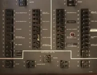
One more electrical question. There was a time marinas had 2 120V 50A hookups. Was there 240 between them? Or were 240 items like the cook top and W/D not available when hooked up to these? The way the panel is set up I don’t see the current making it down to the 240 section. But seems odd you wouldn’t have a stove.
 
Last edited:
They should be 2 different phases with either 208, 220, 230, or 240 V between them. Odd set up even if so. The overcurrent on the dock is at too high an amperage and you are 100% relying on the boats breakers for everything onboard but your cord and adaptors are not protected for anything other than a sudden direct short which would pop nearly any breaker before wires could heat up. If both are the same phase that would mean zero volts between them. All 120 stuff would work but no 240 equipment would function at all.

I am assuming you do not have an isolation transformer capable of producing 240 using a 2 phase (leg really) 50A or single phase 120. I understand how it make the onboard power but have no idea how any of it would work in your situation.
 
Last edited:
Never used any but if there are on opposing phases you should get 240 if using a smart Y just like you can do with 30amp outlets. That I ve done many times at older docks. The smart y will only let power thru if not outlets are on opposing phases

I ve also done it many times connecting a 100 amp to 2 120/240-50s
 
Not sure I understand your question total.
It would depend on how the 120 volt 50 amp pedestal(s) were wired from the main distribution panel.
The two plugs would have to be on two different phases to get 240 between the two.

That said.
My 53' MY is a 1979 (close to yours in setup and vintage).

If I connect to a single 120 Volt, 50 dock plug and connect it to my 120 volt 50 amp service entrance plug on the boat and select that service at the ship's panel it configures the isolation transformer to make 120/240 to the boat.

Keep in mind that in this mode you really only have 240/120 volt at about 25 amps available for use on the boat.

This feature is really great if you are up on the hard in the yard and only have a simple 110/120 volt outlet available. You can at least keep the battery charger and fridge on.
 
I do NOT have transformers. Were I to hook up two 120V/50 connections the two top switches would be selected to the appropriate side. My question is..... what happens at the bottom of the distribution panel at the 220V breakers..... IF the 220V section would get power this way then only if the two shore connections are counter phase would the cook top and the WD work.... Were they always? What if they weren't? I'm suspecting, and hoping more on that later, that the 220V breakers are NOT connected to the 120V section and that ONLY if there is power to the 220V shore power connection will these breakers get power..... The mighty multi meter will answer the question but I thought I'd ask here.
 

Attachments

  • AC Source Panel.webp
    AC Source Panel.webp
    74.1 KB · Views: 214
  • AC Distribution.webp
    AC Distribution.webp
    74.4 KB · Views: 213
Last edited:
if you are using two out of phase 110v connections, they would be on the port or stbd side, not both. And the 220v selector would be switched to port or stbd, matching the side you connected the two out of phase plugs.

Example: You connected two plugs to the 120v connectors on your port side. Then S1 and S2 would be set to port and S5 would be set to port.

Example: You connected a single 220v to your port side. S1 and S2 would be set to 220/110 and S5 would be set to port.

The bottom breakers have no bearing on this, if you connected out of phase power. One leg of the 110 is fed by one cord and the other by the other cord. Both legs feed the 220 section and if they are out of phase you will get 220. If in phase, then 0.

If they are in phase, then turn off the 220v breaker (at the bottom) and don't worry about it.:)

Btw, when you connect a 220v cord, the distribution panel splits it up as if you connected two 110v (out of phase) cords to feed the left and right 110v breaker panels. That is why the 110v stuff is spread across both sides to keep somewhat a load balance. For example, 2 of my 110v AC units are on the left panel and 2 on the right. The two legs are combined agains at the 220v panel. If you turn off the 220v main breaker then you stop it at that point.

Note: All of your 110v breakers at the top seem to be off. You only have a 220v stbd breaker on. Which would be the configuration for a 220v cord connected to the stbd side, not two 110v cords. Unless you are using a pigtail to connect the two cords.
 
Last edited:
All my 110 breakers are ON. There is one 220V breaker on. Yes, I know why we have two "legs" and balance the load and all that.

But......

You are saying that if you connect 2 110V cords there is power to the 220V switch (S5) and if selected to the correct side it would pass the two inputs on on to the 220V breakers? Without verifying that it is in fact 220V? I would find that hard to believe but I'm trying to confirm that I am right.


I was talking about the shore power breakers on your distribution panel at the top. All of the 110v shore power breakers are off.

How would it "verify"? They are just switches and wire. And how would you be able to switch to generator (using S5) if it wasn't involved?

The 220V switch (S5) is kind of confusing, it is THE switch to the breakers below, all of them, including the 110v. L1 feeds one side, L2 the other, and both L1 and L2 the 220v breakers at the bottom.
 
Also, there is no such thing as "220v". 220v is two 110v lines 180 degrees out of phase. That is what we have been calling "legs". Whether you use a single 220v cord that has two legs in it, or two 110v cords (each are one leg) that are 180 degrees out of phase, it is exactly the same thing.

In fact, when a marina supplies two 110v plugs, 180 degrees out of phase, they do so by using the two legs of a 220v line. One leg for one plug and one for another. When they don't do this, then you have 110v lines that are all in phase, which will not hurt your boat, but will also give you ZERO volts at your 220v appliances, because the two legs are in phase and there is no voltage difference across them.

Also, please be careful with your voltmeter, and remember, you are measuring voltage differences. There are 3 key wires. L1, L2 and Neutral. The voltage between L1 and Neutral should be 120v, between L2 and neutral 120v, and between L1 and L2, 240v, UNLESS your two cords are not 180 degrees out of phase, then the voltage between L1 and L2 will be 0v. The 4th wire is ground, and it can act like a neutral, because (on a boat) it is connected to neutral. Thus, you should measure 120v between L1 and ground and L2 and ground.

For you, the key issue is if the voltage difference between L1 and L2 is 240v or 0v. The latter indicates that your two 120v cords are in phase and cannot give you 240v power.
 
Last edited:
I was talking about the shore power breakers on your distribution panel at the top. All of the 110v shore power breakers are off.

How would it "verify"? They are just switches and wire. And how would you be able to switch to generator (using S5) if it wasn't involved?

The 220V switch (S5) is kind of confusing, it is THE switch to the breakers below, all of them, including the 110v. L1 feeds one side, L2 the other, and both L1 and L2 the 220v breakers at the bottom.

All of my 110V distribution breakers are ON. Are you talking about the ones below S5? Yes, those are off as there is no shore cable connected to them.

You are not understanding my question. If I hook up two 110V/50 shore power cord on deck (and turn the associated breakers on) will there be power to S5? It's a yes no answer.
 
Last edited:
All of my 110V distribution breakers are ON. Are you talking about the ones below S5? Yes, those are off as there is no shore cable connected to them.

You are not understanding my question. If I hook up two 110V/50 shore power cord on deck (and turn the associated breakers on) will there be power to S5? It's a yes no answer.

YES

(assuming S1 and S2 are switched appropriately) The power flows through the breakers, to S1/S2, to S5 and then to the breakers at the bottom (AC) panel.

The generator flows through its own breaker, then S5 and then to the breakers at the bottom (AC) panel.
 
YES

(assuming S1 and S2 are switched appropriately) The power flows through the breakers, to S1/S2, to S5 and then to the breakers at the bottom (AC) panel.

The generator flows through its own breaker, then S5 and then to the breakers at the bottom (AC) panel.

Ok. And then in order to get the power to the breakers on the distribution panel you would have to select S5 to the appropriate side (P/SB).
 
Ok. And then in order to get the power to the breakers on the distribution panel you would have to select S5 to the appropriate side (P/SB).

Yes. If power is coming in your port side (regardless if it is 2 cords or 1) then S5 needs to be set to port, and if power is coming in your stbd side, then stbd. And if it is your generator then gen.
 
Yes. If power is coming in your port side (regardless if it is 2 cords or 1) then S5 needs to be set to port, and if power is coming in your stbd side, then stbd. And if it is your generator then gen.

OK, let me get the meter out and verify that next week.

Is everyone else in agreement on this?
 
Last edited:
I am planning on painting from the rub rail over the top to the nonskid. I was thinking of removing the 110v outlets on the toe rail have the wires removed back to the mail breaker panel. I was also going to add an isolator at the same time. Is there a reason NOT to do this. I've owned her for 19 years and have never used them, Thoughts?
 
I've never used them either, nor do I even cary cords for them. And even if you did carry cords, the same thing can be accomplished with a Y-Adapter plugged into your 50A socket.

I think in the day maybe 30A plugs were the norm, thus the two 30A sockets. Just speculation on my part.
 
Last edited:
We have a 1977, 58' yachtfish with same electrical panels a you posted. The 220v feed from port or starboard receptacles will feed through switch S5 both 110v legs and the 220v loads ( stove & washer/dryer). Looking at the electrical diagram,each 110v receptaclecan feed only 110v loads. One receptacle feeds one leg, the other would feed the other leg. Each leg is selected through S1or S2. But i cannot see that those two legs could be combined to create 220v.
 
That is exactly what 240v is. Two 120v out-of-phase lines combined to make 240v. That is how it works in your home as well. In a 240v cord, the two out-of-phase lines (L1 and L2) are in one cord. So, whether you use one 240v cord, or two 120v cords, it is the same thing. That is where the 120v outlets at the marina come from. They are just one of the two lines of a 240v line. What won't work is combining two in-phase 120v lines.

Note: Originally, the voltages were 110v and 220v. Over time, the industry increased the voltages to what we use today, 120v and 240v.

Note: Once in a blue moon (it is rare today) you come across a marina using a 3-phase 208v system, which creates 3 120v lines, but only 208v when combined. Industrial electric (used to run large HP electric motors) is where 3-phase power is used. It's not a good fit for our stuff though, unless you have a transformer.

We know all that. It's a matter of path ways and whether the 110 supplies have a path to the 220 breakers.
 
This is from my Hatteras manual concerning using two 110v cords...

Screen Shot 2021-05-15 at 10.06.13 PM.webp

Note switches S1, S2 and S5.

I never understood why the manual didn't explain things better and just offered a picture. Seems like Hatteras invented IKEA instructions long before IKEA.
 

Forum statistics

Threads
38,156
Messages
448,741
Members
12,482
Latest member
UnaVida

Latest Posts

Trending content

Back
Top Bottom