Sam's is your source for Hatteras and Cabo Yacht parts.

Enter a part description OR part number to search the Hatteras/Cabo parts catalog:

Email Sam's or call 1-800-678-9230 to order parts.

Reengineering an air conditioning unit to “marine” use. Purists should cover their e

  • Thread starter Thread starter MarioG
  • Start date Start date
  • Replies Replies 73
  • Views Views 68,354

MarioG

Legendary Member
Joined
Apr 12, 2005
Messages
1,440
Status
  1. OWNER - I own a Hatteras Yacht
Hatteras Model
58' YACHT FISHERMAN (1970 - 1981)
Reengineering an air conditioning unit to marine use. Purists should cover their e

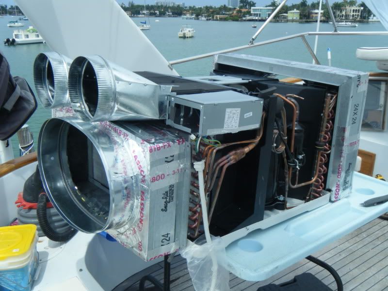
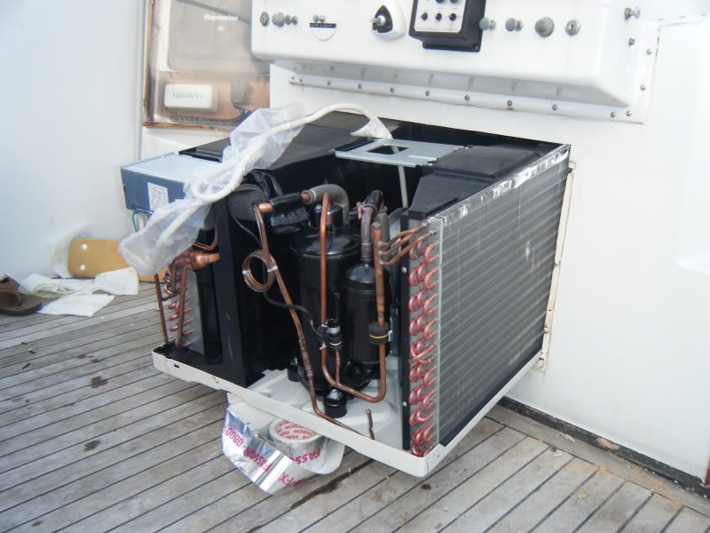
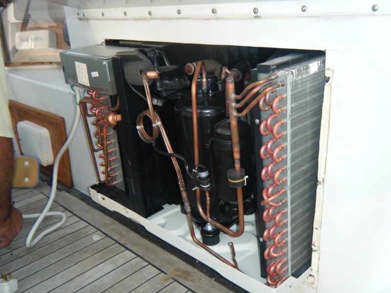
Finally, after taking a hammer to the P.I.T.A. aft salon air conditioner for the last time, I sat down and cooled off with a beer. I started to rethink this whole “marine” a/c theory and the way it is used in our application. Truth be told, this idea was thrown around last year with my good friend Hector. Hector, like me is gear head and we both share the same pastime of fixing or reengineering anything. Not being afraid of failure and with time on my hands we set out to rethink this “Marine” A/C system. Specifically how we can redesign a system conveniently and affordably with the added advantage of lower maintenance. Our old system for our salon cooling consisted of a 16K btu aft salon A/C and a 14K btu forward salon A/C that is also ducted into the galley. On a good day with both salon units working, it could barely keep up with the blistering heat and humidity down here in south FLA. especially when having a large amount of family and friends aboard. Both units were clearly showing their age and were starting to be a maintenance headache. The cost to replace both units with a substantially larger unit was through the roof which also required me to run larger Freon lines and change to 220V. This would have required me to remove the port side sofa and remove the original teak wall paneling to run new lines. Something that I wasn’t in the mood for. Another problem with the OEM units was that both A/C’s while operating were very loud due to blowers located inside it’s cabinets. Also it is poorly designed in that the a/c cabinet is located at knee level and blows cold air up to the ceiling instead of from the ceiling down which is more efficient use of cold A/C. After several months of searching we came to the conclusion that a departure from a “Marine” system was needed. Domestic systems were readily available and with a large variety and styles around, it opened up possibilities. So we created a short list of what was needed and what goal we were shooting for. The list consisted of cost, ease of maintenance, simplicity of reengineering, low amp draw, minimal/ low impact to factory (Hatteras) interior structures, cosmetically conservative. We looked and studied split systems, mini split systems, window shakers and wall units. All having their pros and cons. But after a thorough study and crunching numbers over and over we came to the conclusion that the unit that best fit our criteria for this redesign experiment was a LG 24,800btu Mod: LW2510ER window unit. After initially scoffing at the idea and the thoughts of the Beverly Hill Billy’s running through my mind, I put on my thinking hat and focused on the task at hand.
DSCF2334.jpg

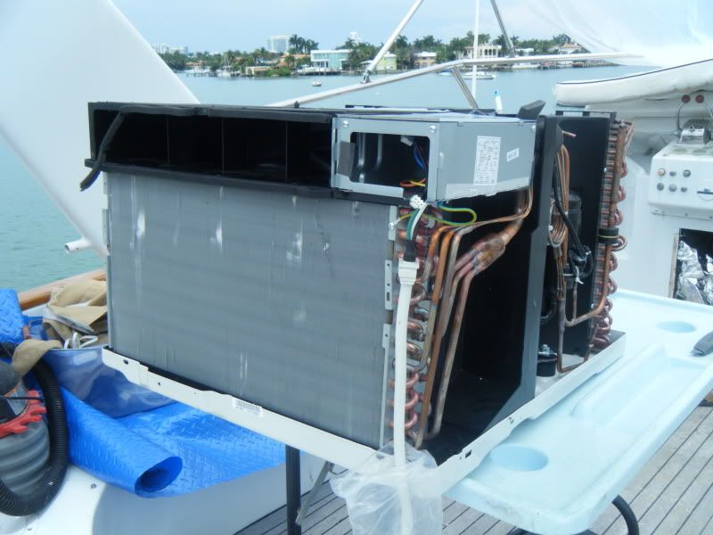
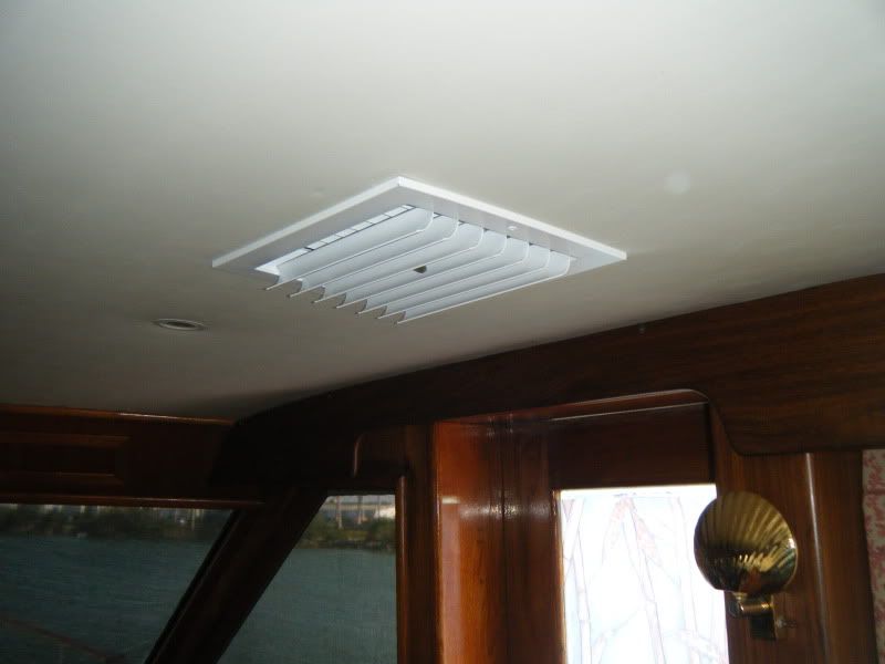
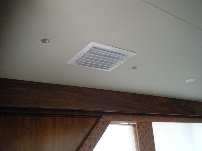
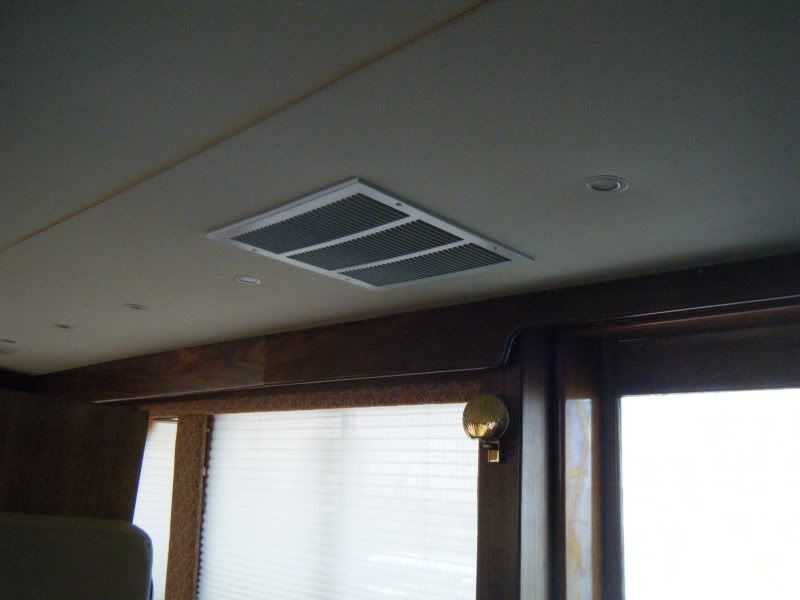
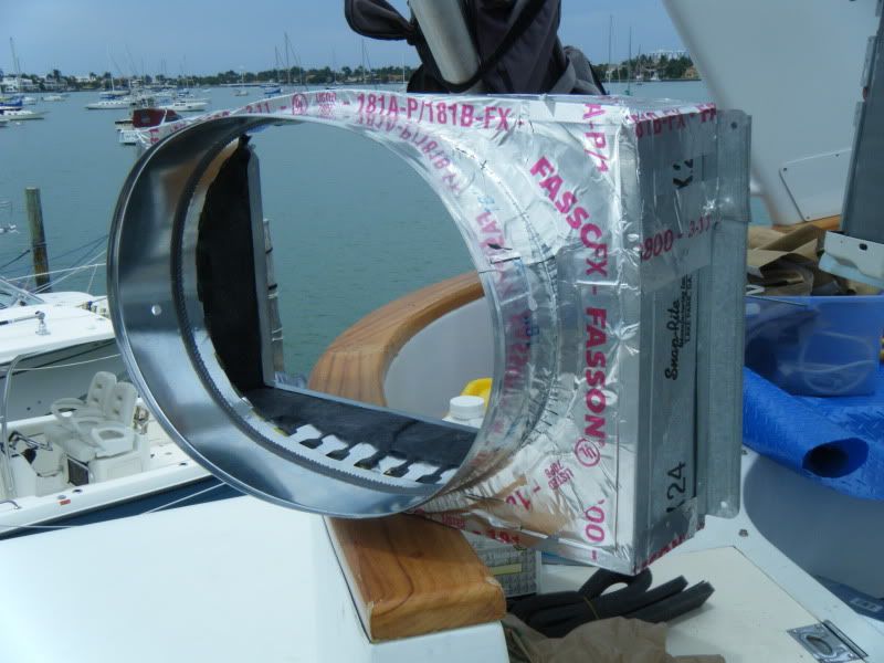
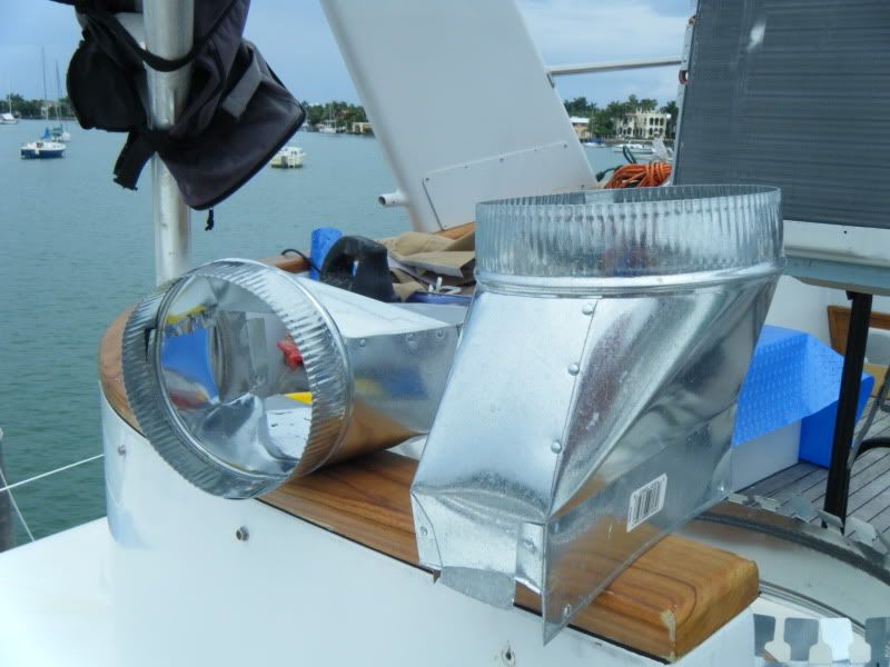
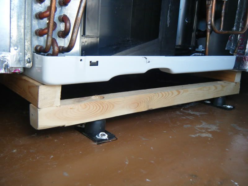
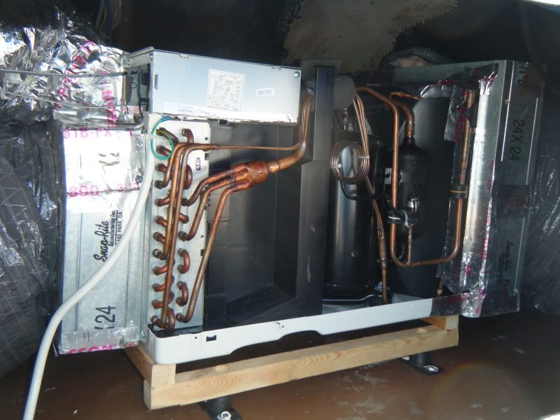
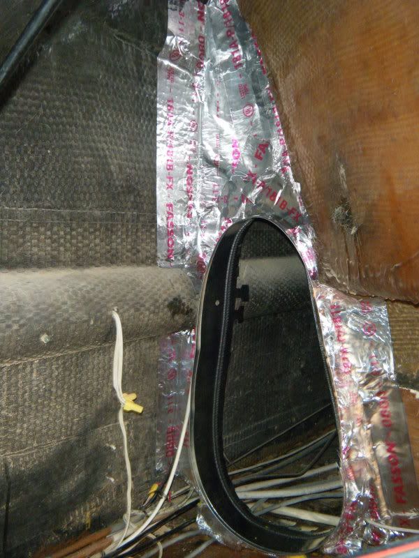
FYI, I always had a back -up plan incase this experiment failed miserably or did not live up to my strict expectations. I was fully prepared to junk this project, bite the bullet and install a “marine unit”. With this in mind I started with the duct work. Wanting to use a more efficient method of ducting, we chose to access the interior of our fly bridge to install A/C vents using insulated 8” and 16” ducting. Having a large fly bridge interior made this a fairly easy task. First I cut three holes into the fly bridge floor/salon ceiling with a router and after removing the balsa coring and epoxied the remaining exposed balsa around the circumference of the opening, I fiber glassed in two 8” galvanized ducting collars and a 16” ducting collar for the return air.
DSCF2344.jpg

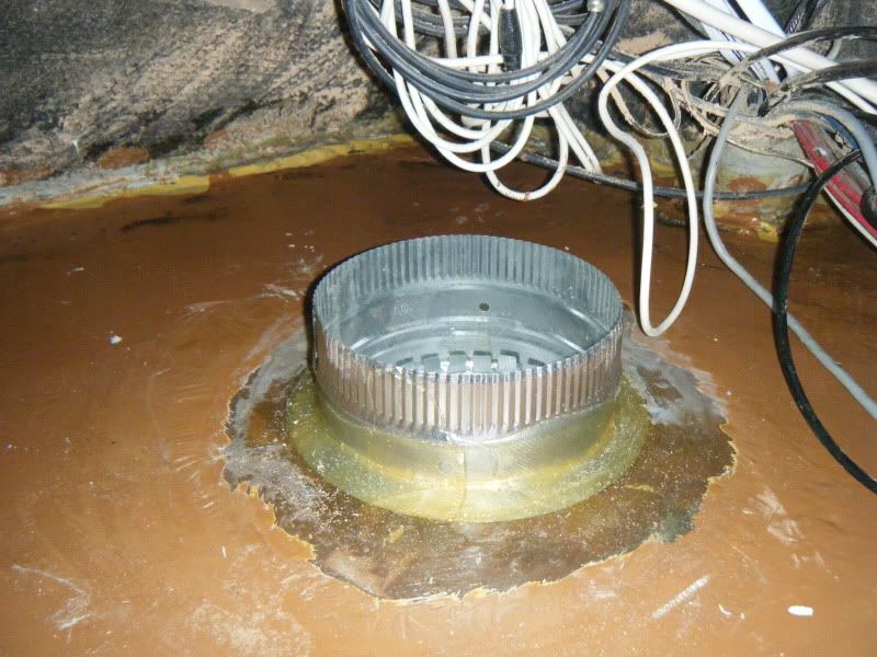
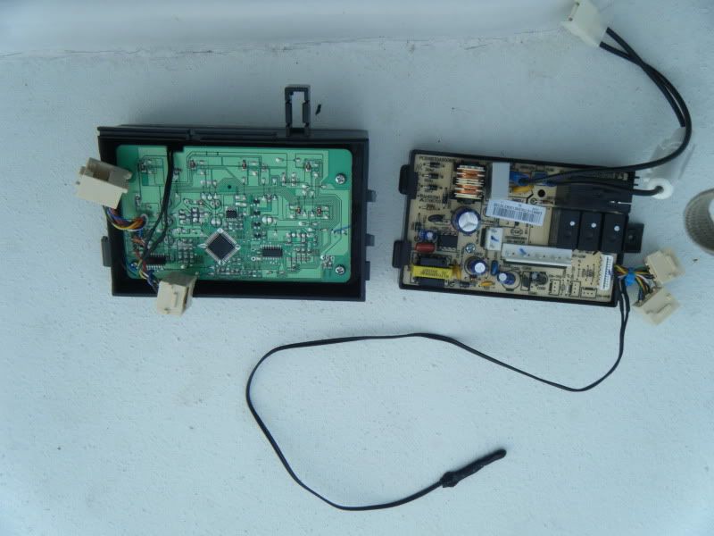
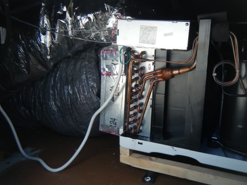
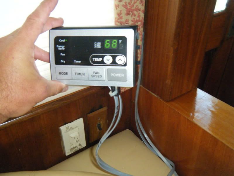
Believe it or not this part of the project was probably the hardest and the one that required the most thought because you needed to precisely place the vents between the salon lights while not cutting into the wiring. FYI the ceiling is about and 1 1/2” thick (1/4” of fiberglass, 1” of balsa, another ¼” fiberglass). After installing the collars, I ran 20’ of clear hose and 50’ of 3 wire 12ga boat cable for power through the starboard rubber wire conduit in the fly bridge which leads down through a teak wall conduit next to the starboard passageway door and into the starboard engine room. The hose was connected to a bilge drain manifold located on the engine room wall. The wire was run all the way to the 220v breaker panel. After that I ran two ribbon type RJ47C communication wires of approximately 15’ each down the port side wire conduit in the fly bridge to the area of the salon light switches that are located on the wall behind the port couch next to the port passageway door. This wire will be the harness that will be connected to the electronic control panel that was removed from the front of the A/C unit which will be remotely mounted. The final grunt work was installing the insulated ducting to all of the collars including a 16” insulated duct to a collar located down the starboard hollow interior wall of the fly bridge (more on that later).
DSCF2350.jpg
 
Last edited:
Re: Reengineering an air conditioning unit to “marine” use. Purists should cover the

This part of the project so far on a scale of 1 to 10 (10 being hardest) in difficulty was about and 8 due to the precision of cuts in depth and location, and fiberglass work.
DSCF2360.jpg

DSCF2362.jpg

DSCF2361.jpg

After installing the interior a/c vent grills, the focus was turned to the a/c unit. We started by removing the unit from its exterior case (cabinet) followed by carefully removing the computer board and the controller from the front of the unit.
DSCF2334.jpg
 
Re: Reengineering an air conditioning unit to “marine” use. Purists should cover the

While Hector worked his electronic engineering magic on the control panel wire harness and plugs. This unit has many advantages which made customizing a snap. First the condenser fan is shrouded like the radiator fan in your car.
DSCF2343.jpg

This is a very important consideration because for the unit to work properly outside of its cabinet the condenser must have fresh air directed into one side of the condenser (fan side) then out the other side at a much hotter air temperature. For our purpose, the fan shroud meant that I only had to isolate expelled hot air from mixing with the fresh “cooler” air that entered it, i.e. not circling back around into it. Secondly, the construction materials of the unit is mainly composed of copper, plastic and power coated components. Very little to corrode. Thirdly the front of the unit where the conditioned air discharge vent is located can easily be adapted to accommodate two Home Dpt off the shelf vent-to-duct tin 8” collars where the insulated ducting will attach to. Thirdly, this unit has the most btu’s for its overall dimensions.
The first step to ducting the unit is to enclose the return air in an insulated vent box. These are the boxes that come in various sizes and are basically a tin frame surrounding fiberglass insulation board. These can be found at your local refrigeration/air conditioning shop. The only problem I found with this was that there wasn’t a box that had the proper dimensions as the evaporator and the condenser. Although these boxes can be custom made by the a/c shop for a nominal fee, it would set me back a week. Therefore, I just bought 2- 24x24 vent boxes and cut them down to size. Very easy but be careful, it’s very sharp when cut. To properly attach the vent box onto the evaporator requires some sniping of tin from the box to get a good attachment point via two rivets onto the bottom of the cold air discharge vents. Note: be careful when drilling/riveting in close proximity to either the evaporator or the condenser. One slip, one hole, game over. Once the return air box is properly fitted, you can cut out the insulation board and install the 16” duct collar.
DSCF2335.jpg

Note this shape will take on an oval shape. Don’t worry it’s ok. Now you can fit the vent-to-duct tins to the cold air discharge. These vents are almost perfect in size and only requires some minor cutting to install into the discharge vents.
DSCF2338.jpg

For simplicity and efficiency pop rivet both vents together and tape the inside wall of the vents together. Complete the same vent box procedure with the condenser. Two very important notes at this point, first, all fitted vent components MUST NOT be permanently installed yet! because fully assembled the unit is much harder to maneuver into the fly bridge. All components will be permanently installed once the unit is in its final location. Basically you are pre fabricating the parts for installation later. Secondly, once you have constructed the boxes and vents, they may feel flimsy at first but this will go away once you apply aluminum ducting tape and rivets. This stage of the project, rated on the difficulty scale is about a 5. At this point you are 80% complete.
DSCF2339.jpg
 
Re: Reengineering an air conditioning unit to “marine” use. Purists should cover the

Returning to the electronic panel, Hector carefully and painstakingly soldered each thin wire to the back of the electronic board where the original factory ribbon wire was plugged into. Phone jack type plugs were used to attach both ends of the long wire harness from the electronic control panel to the control box in the unit.
DSCF2352.jpg

For ease of installation, at this time the control board was reinstalled back into the control box on the unit. Before installing the unit, a soft mounted frame needed to be built. This is actually one of the most important aspects of the project. The frame was built using 1-1/2x1-1/2 wood studs cut to 24” and screwed into a square frame. Soft, neoprene isolation damper mounts from Grainger were used to isolate any vibration the unit may produce while operating.
DSCF2347.jpg

DSCF2349.jpg
 
Re: Reengineering an air conditioning unit to “marine” use. Purists should cover the

The height overall is about 6-1/2” from the base of the mount to the top of the frame. The height is critical because of the condensation drainage requirements. This part of the frame installation and unit requires help and patience. Proper installation of the frame must take into consideration the natural curve (crown) of the roof. The mount must be placed offset from center to starboard so that the unit takes advantage of the curve to aid in proper condensation flow to the drain. This step will require a slender person due to tight confines once the unit is inside the fly bridge. It is imperative to install the unit on its mount as far forward as practical in the fly bridge.
DSCF2353.jpg

DSCF2354.jpg

Once mounted the unit can be slid side to side on the frame to screw the mounts to the roof/deck.
DSCF2358.jpg
 
Re: Reengineering an air conditioning unit to “marine” use. Purists should cover the

Finally firmly attach brackets and clips to avoid movement during rolling and pitching. Now you can permanently install the vent boxes and air vents. Do not skimp on tape at this critical point not only will it give it structure but more importantly the unit must be sealed well to avoid outside air from being suctioned into the return air. A tight seal is important for efficiency. Take your time. Install your insulated ducting to all the collars. Tape, zip tie, then tape again the ducting to the unit.
DSCF2356.jpg

DSCF2357.jpg

Install the plastic barb drain fitting with fast dry 3M 5200 to the back of the unit drain pan through the hole that you cut into the vent box you made, don’t mess this up or it will drip water. Attach drain hose. This stage of the project rated on the difficulty was a 7. Finally, plug in the control panel wire harness and 220v power but make sure the breaker is off. Back in the salon all that is left is to plug in the other end of the wire harness to the control panel.
DSCF2363.jpg

At this point you can turn the breaker and start the unit.
Results:
The salon now has plenty of conditioned air! From a performance standpoint, the unit has a wide range of cooling temperatures while properly cycling on and off. In fact, the salon can easily maintain 68 degrees during the day and 70 at night. Humidity is noticeability way lower. But where the real added advantage is that the factory aft salon a/c and the forward salon a/c is no longer needed! Not only did it cut down on the noise but the power savings is huge. As an example, with the master room, guest room, forward salon and aft salon A/Cs operating I was pushing close to 50 amps. Now I’m drawing about 28 amps total! As far as noise and vibration from the new unit, all that is perceptible is the quiet flow of air coming from the vents. No rumbling, no vibration. When the compressor kicks in it sounds like it’s very far away.
The only structural modifications that were made besides installing the A/C vents overhead in the salon was to the fly bridge access door. I did have to cut approximately 1” of the opening once the door frame was removed to accommodate the unit. It is now being replaced with a louvered door to aid in unit cooling. The other modification was to the starboard aft section vent of the fly bridge. Normally this vent was to keep the inside of the fly bridge dry with airflow. Now the vent was enlarged to allow warm air to escape and not return or flow back around to the unit. A new custom made louver is being fabricated.
Final thoughts,
My total investment in this project is about $800 or so. It took me about two weeks to prepare, engineer and install. From an esthetics view, it is clever design that looks quite good. With what I have learned I believe that this project can be done in about a week to 10 days as a DIY project. This project is totally practical from an application standpoint and has exceeded my expectations. Clearly one needs to get over the whole “marine” label that only serves to cost us substantially more. Also a willingness to think outside the box is a must. This project is totally doable and very gratifying.
Enjoy! Mario
 
Re: Reengineering an air conditioning unit to “marine” use. Purists should cover the

Eagerly awaiting the comments from spcoolin and many others.....congrats for being inventive, hope it lasts and works well.
 
Re: Reengineering an air conditioning unit to “marine” use. Purists should cover the

Mario, first of all CONGRATS on a low cost solution to your A/C woes. My only concern is if you have given enough consideration to the amount of heat that will be coming off the back side of the unit. Where does it vent? Will you be able to drive drom the flybridge during the summer with the added noise and heat? Ther will be ALOT of heat coming out and you may have to drive from below even when you may want to be up top. Just a thought.

GOOD LUCK!
 
Re: Reengineering an air conditioning unit to “marine” use. Purists should cover the

Great Job, with a few thoughts.

1. It is probably a little too efficient. Meaning if your yacht is really tight and you crank it down to 68 and it sucks all the moisture out and your 25 uncle Marios are snoring there fool heads off they may not wake up. At least that is the theory. You can check online but there is a ratio of inside and outside air that needs to be changed over. It is also interesting reading when doing A/C design.

I always figured our boats were so low on the BTU side and had little ability to dry anything out and they were not sealed up very well. Plus they were built a long time ago. That no worries.

2. It has to survive vibrations it would never see in a house and "G" shocks that it would also not see in a house.

But I love the idea it is great! You could get ahold of a manufacturer in a place far far away, design the specs, come up with some lighter weight materials, able to handle vibration and shock load buy 100,000 for 40 dollars and sell them for 400 dollars and be rich rich rich. Until uncle Sam hears about it and taxes you to death and forces you out of business like he is doing to everyone else. But I digress.
 
Re: Reengineering an air conditioning unit to “marine” use. Purists should cover the

I believe 10 deg F is maximum recommended temp diff, inside to outside.
 
Re: Reengineering an air conditioning unit to “marine” use. Purists should cover the

Mario, first of all CONGRATS on a low cost solution to your A/C woes. My only concern is if you have given enough consideration to the amount of heat that will be coming off the back side of the unit. Where does it vent? Will you be able to drive drom the flybridge during the summer with the added noise and heat? Ther will be ALOT of heat coming out and you may have to drive from below even when you may want to be up top. Just a thought.

GOOD LUCK!

Thanks Byron,

As far as the heat. I too thought of it. the heat given off the back of the unit is ducted away. The duct is through the inside of the fly bridge wall leading aft. The hot air is vented out the back of the fly bridge wall facing aft and is far enough away that the warm air is not felt. infact the reverse is happening. due to the volume of fresh air entering the fly bridge through the flybridge access door under the helm you can feel the flow of fresh air around your feet at the helm station. besides the warm air volume isn't all that much and is desipatated quickly.
 
Re: Reengineering an air conditioning unit to “marine” use. Purists should cover the

Great Job, with a few thoughts.

1. It is probably a little too efficient. Meaning if your yacht is really tight and you crank it down to 68 and it sucks all the moisture out and your 25 uncle Marios are snoring there fool heads off they may not wake up. At least that is the theory. You can check online but there is a ratio of inside and outside air that needs to be changed over. It is also interesting reading when doing A/C design.

2. It has to survive vibrations it would never see in a house and "G" shocks that it would also not see in a house.

.

during my research I did read up on that. But I figured that our boats aren't no where air tight to begin with. my uncles should be fine.

as far as vibs and shocks I did take precautions during the mount design. But I agree, but only time will tell.
 
Re: Reengineering an air conditioning unit to “marine” use. Purists should cover the

i MUY BUENO PARA USTED ! I always appreciated thinking outside the box. You are to be commended, cabron!

That new unit probably has a radial compressor... way quieter than the old recips. Make sure the new units differ in that the old ones would run the lip of the exhaust fan touching the condensate, thinking the water will help in exchanging heat. Check for water spray and condensation in the helm.
I painted my top last winter and installed a pair of louvered vents on the outside also... some thing you may want to consider.
(glad your typing improved!! ;-)) )! That was quite an essay. ws

2laqvzb.jpg


slivq9.jpg


ddgzkl.jpg


2qltzyx.jpg


Nice powder coated window frames etc...
 
Re: Reengineering an air conditioning unit to “marine” use. Purists should cover the

Since air is a better heat conductor than water and new marine units (24K BTU) are not what you wanted it probably works. Like bolting 3 outboards to the transom of a 36 foot inboard boat. I think there are other options but its your boat.
 
Re: Reengineering an air conditioning unit to “marine” use. Purists should cover the

The phrase "Shock and Awe" comes to mind....

Kudos for your creativity and for having the chutzpah to share it with the expurts and purists here. We'll be expecting a long-term evaluation and report some time in the future. Meanwhile, reward yourself by enjoying a frosty beverage in air conditioned comfort. :D
 
Re: Reengineering an air conditioning unit to “marine” use. Purists should cover the

exchanging heat. Check for water spray and condensation in the helm.
...


Thanks Willy! No water spray in te helm. bone dry. It's been running for over a week. No issues. So far...
 
Re: Reengineering an air conditioning unit to “marine” use. Purists should cover the

The phrase "Shock and Awe" comes to mind....

Kudos for your creativity and for having the chutzpah to share it with the expurts and purists here. We'll be expecting a long-term evaluation and report some time in the future. Meanwhile, reward yourself by enjoying a frosty beverage in air conditioned comfort. :D

Thanks! Yes this will be an on going case study and I'll report the good and the bad. It does give me the giggles when I think about it though...

Ps. thank you for thinking up the name. air to air "marine" A/C. Shock and Awe series
 
Re: Reengineering an air conditioning unit to “marine” use. Purists should cover the

Mario...you are my air conditioning hero!!! LOL I've been waiting for this thread and the photos. Muy excellente, mi amigo!

Guess what crapped out on Sanctuary???? The blower unit for the pilothouse. Guess how we're going to fix that! It will be nice to have a nice deep cabinet in the pilothouse when I yank out the evap unit....and that spot in the ER where the compressor sits right there at the door...tool box!!!

I have a huge vacant area under the FB helm and it's directly over the entire pilothouse and then some. And if we install our AC unit up there to starboard, maybe I can cure that list to port afterall. Somewhere up there, we already have 220v power because the FB has an AC unit which I'll be removing. We never use that - it's just extra weight that can go away.
 
Re: Reengineering an air conditioning unit to “marine” use. Purists should cover the

Great job and thanks for sharing. Anxious to see what the long term results are. I've thought about doing something similar in the past but never had a need for it. Your design is not too different than what I have on my boat. I have a marine AC unit but the air handler is under the Fly Bridge apron. on my boat there is a door and tons of room in there. I have one large return similar to yours and the cool air comes out of the window valances. Haven't really taxed it yet but it keeps the salon at 68 when it was in the 90's and humid in Fl.
 
Re: Reengineering an air conditioning unit to “marine” use. Purists should cover the

This is a great idea. Isn't this similar to what buses and motor homes use? Air to air heat pumps, basically?

By the way, water is a much better absorber of heat than is air. The specific heat capacity of water is much larger than air- it both cools and heats better. Fifty degree water has a lot of heat energy in it, which is why water to air heat pumps work; fifty degree air has far less. None of this is a problem in FL where your aim is to get rid of heat, not keep it around.
 

Forum statistics

Threads
38,156
Messages
448,741
Members
12,482
Latest member
UnaVida

Latest Posts

Trending content

Back
Top Bottom