Sam's is your source for Hatteras and Cabo Yacht parts.

Enter a part description OR part number to search the Hatteras/Cabo parts catalog:

Email Sam's or call 1-800-678-9230 to order parts.

Boat AC ground wire not connected??

  • Thread starter Thread starter brico
  • Start date Start date
  • Replies Replies 32
  • Views Views 5,579

brico

Well-known member
Joined
Dec 25, 2013
Messages
311
Status
  1. OWNER - I own a Hatteras Yacht
Hatteras Model
37' CONVERTIBLE (1977 - 1982)
Hi, I opened up my shore power connection box to check the wiring and see if there is merit in replacing the "shotgun" fuses with newer style breakers as my transparent fuse covers are cracked and a bit "weathered'. As I opened it up I noted that the green "Ground" wire was not connected at the back of the shore power "G" connector terminal and that it was taped over by electrical insulating tape. Would anyone have any suggestion why would someone not connect the boat's AC supply power ground wire at the "G" terminal on the back of the shore connector plug?

Also, I am not really good with electricity and got a bit confused looking at the AC supply power wiring arrangement. I noted that one fuse is on the Phase wire and one is on Neutral wire. I have read somewhere that the only reason why one would fuse both Phase and Neutral wires is if there is possibility of polarity reversal. That is, where the phase and neutral conductors could be interchanged on the supply side of the fuse. If polarity reversal is possible, then double-fusing guarantees that the phase conductor will always be provided with a fuse.

Is there a possibility to interchange the Phase and Neutral on boat's shore power connection if all three pins/slots (male/female sides) on the shore power cable connectors are different shape and size and cannot be interchanged?

Any insight and suggestions are welcome.

 
Last edited:
If the shore power is wired wrong, you could have reverse polarity. Also, if someone wired the end on the plug wrong, you could also have reverse polarity. The ground wires should be connected as well.
 
Ground wire in AC systems are extremely important, I would say. 30mA could send you on eternal patrol.

There are two ways of grounding the boat.
One, is the most common, to continue the shore ground wire to the ships AC system.
The downside is that shore systems or circuits, that you happens to be hooked up to at the moment, may have ground faults. Then you transfer that ground fault to your boat if you have no protection.

Two, is to have a boats own grounding system, then shore grounding is cut in the intake box.
Then you need to have (I like two, stb & port) grounding plates on the bottom. They are about the size of an IPad.
These plates are made of a sintered brass alloy. That means they have a physical surface area of about 2m2, two plates are 4m2.
The wires from these plates are connected to AC grounding screw in the distribution/ fuse cabinet like a shore grounding wire.
The requirement for AC grounding is that they shall be >0,25m2.
What US (UL) requirements are I do not know. By using the plates you have full control of your grounding condition. Between live and ground you should read 115 divided by square root of 3.(if 3 phase generators are used for power production.)

In an AC system you can not have reverse polarity. The current change + and - 60 times a second.

you should follow wire codes, but in reality it will work fine regardless of what terminal the wires go to. (just mind the ground wire)
Look at a receptacle and a plug (unearthed). You can put the plug in either way both works fine.

Reagards
Oceantop

I don't think any of this post is valid, except where you say that having ungrounded shore power is dangerous. I think you are confusing a grounding plate, that is used with radios and lightning protection, with AC grounding. I also think you are confusing AC polarity with DC polarity.

Grounding and Polarity are all about SAFETY. You can screw them up and everything electrical still operates, but you have the potential for a serious shock hazard.

The ground wire in AC systems is used whenever there is the chance that the chassis of the device or appliance could possibly come in contact with the AC power, through a wiring fault or a short for example. If the device or appliance is properly grounded (via the green wire) then such a fault will send the current back through the ground wire and usually also trip the circuit breaker. Plastic devices like TVs etc, have little chance of having this issue and thus usually do not have three prong cords.

A grounding plate in water cannot serve this purpose and would instead electrify the water if there is a fault in your boat's electrical system.

Polarity in AC systems is more nuanced but it insures that the neutral (white) wire is at the same GROUND potential throughout the boat. The neutral wire is called that because it is GROUNDED. It is true that AC current alternates, but it is driven through the black HOT wire, not the neutral WHITE wire. I do not suggest this, but technically, you will not get shocked by the neutral wire. Where this comes into play is when you design an appliance, you put the On/Off switch on the black HOT wire where it enters the appliance. Thus, when you turn the appliance off, it is off at the very start. If you wired it in reverse (reverse polarity) then it will still work but when you turn it off, the wiring in the appliance will still be energized. It is still off as in it isn't using any electricity, but most of its internal wiring is still hot. But there is more to this, such as the fuses and breakers are on the HOT wires, not the neutral wires. Thus, when one blows, the wiring is not energized. If you put the fuses on the neutral wires, they would break the circuit but still leave everything energized.

Grounding and polarity are very old concepts and have covered 99.9999% of the hazards. Obviously, with boats and water there are other issues as well, where adding isolation transformers etc. makes sense.

The OP should have an electrician check out the shore power setup. Obviously an electrician with marina experience.
 
Another significant example regarding polarity. If your polarity is REVERSED, when you switch off your breakers, you haven't switched off the power. Your wiring will still be HOT. All you have done in this case is switch off the neutral (ground). That will obviously turn off things, but the wires will still be energized and will still kill you if you touch them.

When the polarity is correct, then when you switch off the breakers, nothing is hot, except the line to the breaker.
 
"Also, I am not really good with electricity and got a bit confused looking at the AC supply power wiring arrangement. I noted that one fuse is on the Phase wire and one is on Neutral wire. I have read somewhere that the only reason why one would fuse both Phase and Neutral wires is if there is possibility of polarity reversal. That is, where the phase and neutral conductors could be interchanged on the supply side of the fuse. If polarity reversal is possible, then double-fusing guarantees that the phase conductor will always be provided with a fuse."

As I wrote earlier, you want the fuse on the HOT wire so that when it blows the boat is not HOT. What you suggest would not work because only one of those two fuses will blow first and it could be either one depending on which one was slightly quicker to blow. As soon as one blows, the circuit is broken and the other fuse would remain connected.


"
Is there a possibility to interchange the Phase and Neutral on boat's shore power connection if all three pins/slots (male/female sides) on the shore power cable connectors are different shape and size and cannot be interchanged?"

The possibility of reversed polarity isn't necessarily with plugging it in wrong, but with the wiring of the pedestal itself. To check polarity you simply use a voltmeter between the two power wires and the ground wire. The hot wire will show voltage and the neutral wire will not. If the neutral wire shows voltage and the hot wire not, then your polarity is reversed. Generally, you check between the hot and neutral, hot and ground, neutral and ground. The first two should show voltage and the last one should show no voltage.
 
I m puzzled by that nr2 post as well. Yes reverse polarity is possible and dangerous

Shore power ground should always be connected. I can’t imagine why it would have been disconnected. It needs to be reconnected ASAP
 
I actually did some research, because that post was so backwards, and it is possible that the poster is from a European country that only relatively recently (1997) adopted the grounding standards we are so used to. In an AC system without grounding, the concept of ground, neutral, and polarity are meaningless. Thus, I can understand some of his comments, except one. I would never ground a bonding plate to my AC system unless that system wasn’t also grounded to shore power. To do so introduces the real possibility of electrifying the water without any indication that you have done so. It would be far better to not have any ground. Just use two wires, hot and hot.
 
Last edited:
Grounding plates are perfectly good and safe for AC systems on board boats and ships as long as the active area is large enough. The obvious reason we have to use grounding plates on the Hatters boats is that the grp hull is not a conductor. The plates are just as safe for shore power as for the on board AC generators. What is taking care of the grounding when the generator is driven en route?

Commercial ships are all using auxiliary engines continuously producing AC power. Usually the power production is 440V 60Hz, but on smaller boats you can also find 230VAC or 115VAC. 440/60 is also normally used on the largest tankers and bulk ships.

These commercial ships needs grounding for safety. What do they use? Yes, the ocean. If it is a steel hull they do not need earthing plates at all. The steel hull acts as 100% grounding.
Some smaller ships may be made of GRP, they needs grounding or earthing plates.

Sea water is an extremely good conductor.
Even when you build a house or factory you need to make your own earthing system which must be approved by the power company and UL.
If you happen to erect your house or factory close to the sea you can lay a copper coil in the sea for the best earthing.
If the water happens to be fresh it must be ultra clean before you loose it’s conductivity.

appliances as phone chargers, electric drills and a lot more may be double insulated. They are identified by one square outside a smaller square on the nameplate. These require no grounding.
Most items with conductive cover usually needs earthing. All items with an earthing plug must be connected to earth.

The AC earthing or grounding plates must not be confused with the boats DC ground.

Personally I do not like the minus to ground system on larger boats, or plus to ground that also can be found. i am working on a Hatteras 53 MY for the time being. This boat is originally equipped with a 32VDC system and a 230VAC generator.
I removed every single wire in the boat, AC and DC, instrumentation, and navigation system.
Over the years the electrical systems plates as described.

Earthing plates were already installed on this boat ( perhaps all Hatteras with AC generators have them?)

Dc 32V is changed to 24Vdc insulated 2wire system. That means no metal on the boat is part of any electrical system.
However all the metal, engine blocks, tanks, shafts, rudders and anodes are connected together in order to equalize any potentials. The items that needs chassis ground like antennas and some navigational items are also connected here. This ground is also connected to the sea, but not physically to any AC grounding.

The system as here described works fine and is according to rules and regulations. I have done so on other boats to.

Regard
Oceantop

Ships Electrical Engineer
Electronics and Automation Engineer, Offshore systems world wide.
 
I forgot to say that I am looking at the shore power from an European perspective.

But the on board system depends on the generator, if it is a three phase generator or a 1 phase generator, and which system is used for distribution of 1 phase from 3 phase is a factor.

What Intention Hatteras had with the earthing plates I do not know. But are they large enough they can handle all power or current that needs an escape to the ground.


Oceantop
 
“ What Intention Hatteras had with the earthing plates I do not know. But are they large enough they can handle all power or current that needs an escape to the ground.”

I’m sorry, but that is entirely false. You should check with an electrician, before you kill someone. And this has nothing whatsoever to do with generators. The earthing plates you speak of would be for SSB radio. And at most, they would have been connected to DC, not AC, unless your AC was grounded to shore power. Think about it. If you are using the water as ground, then if someone is swimming in the water and your boat has a an issue (which is the only purpose for grounding) then that current will flow through them. You see, the point isn’t can they ground, but the danger of grounding through the same water that someone might be swimming in.
 
Last edited:
I have done some wire tracing and research of the Hatteras blueprints. The Green ground wire not connected to the back of the shore line plug is wrong and I have reconnected it back.

The original blueprint shows a power line going from the back of the shore power plug (B,W,G) going into the transformer and the ground Green wire is connected onto a bolt on the transformer case, as are two more Green wires. One from the (B,W,G) line going out from the transformer to the shoreline power panel inside the boat and the third Green wire (short jumper) from one of the Transformer jumpers.

The original blueprint clearly states:

7. THIS IS A 120 VOLT 2-WIRE (PLUS GROUND WIRE) DISTRIBUTION SYSTEM.

THE SHIPS SERVICE AND GENERATOR SECTION ARE PLOARIZED BY NEUTRAL GROUNDS AND THE SECONDARY OF THE SHORELINE TRANSFORMER AND THE GENERATOR, RESPECTIVELY. BY USE OF THE TRANSFORMER, THE SHIPS SERVICE SHORELINE IS NOT POLARITY SENSITIVE.

While it still puzzles me why would someone purposefully not connect the Green wire at the back of the shore line plug as indicated on the original blueprints, I believe who ever did it was wrong but did not cause damage by doing so.
 
What you have is a polarity transformer. That is why they state that the polarity does not matter.
 
What you have is a polarity transformer. That is why they state that the polarity does not matter.

Was the polarity switching such and issue in 1980s when this boat was built wit that transformer installed or the transformer was put in for another reason?
 
Was the polarity switching such and issue in 1980s when this boat was built wit that transformer installed or the transformer was put in for another reason?

It still is. People connect the outlets up backwards all the time, and without using a voltmeter, there isn't any way to tell. Everything works just the same. It's just dangerous.

Also, the ground wire should never be disconnected at the pedestal. If your boat had an isolation transformer (different from a polarizing transformer) then it would simply not use the ground wire. But the pedestal would still be wired with it.

Would the transformer box not be grounded?
 
It still is. People connect the outlets up backwards all the time, and without using a voltmeter, there isn't any way to tell. Everything works just the same. It's just dangerous.

The boat yard I was working in did this. I was kneeling on wet gravel and grabbed the prop with both hands to rotate it - Wow! Good thing I didn't die, nobody else was around that Sunday morning.
 
I would highly recommend contacting Hatteras to find out about your particular boat. On my 1979 53 MY, my electrician almost crapped himself when he found this exact situation. After contacting Hatteras directly they confirmed that when my boat was made this was the correct wiring. The on board transformers took care of the ground. I don't pretend to understand it but after doing some extensive research with ABYC my electrician agreed that at the time is was up to the standard and we decided that after 40+ years of functioning properly we'd leave it as it was designed. YMMV
 
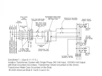
Maybe the attached schematic from AYBC might help clear things up a bit regarding the connection of the ground (green wire) and the Neutral (white wire) on boats with an isolation transformer application only?
  • This is for a single phase 220/240 VAC input transformer isolated boat supply only.
  • The green (groundING conductor) from the shore pedestal is ONLY connected to the transformer's internal shield and NOT to the boat's ground and/or neutral system.
  • The white (groundED conductor) from the shore pedestal does not connect to anything on the boat electrical system.
  • The ground and neutral system for the boat originate at the output "center tap" of the isolation transform. Note: This is the only point the two are connected together.
This is how my 1979 53' MY was wired from the factory and also what the original schematics and black diagrams call out. Of course other years and models may be different.
diagram7.webp

When there is no isolation transformer used both the neutral and ground wires are connected from the shore power plug to the boat's electrical system but never connected together on the boat. ABYC is pretty specific on how that is connected also.
 

Forum statistics

Threads
38,152
Messages
448,690
Members
12,482
Latest member
UnaVida

Latest Posts

Trending content

Back
Top Bottom